Toyota Corolla Cross: Removal
REMOVAL
CAUTION / NOTICE / HINT
COMPONENTS (REMOVAL)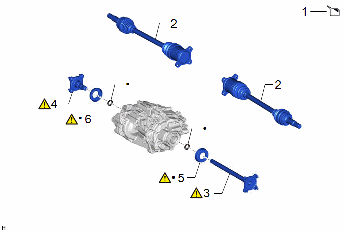
|
Procedure |
Part Name Code |
.png) |
.png) |
.png) |
|
|---|---|---|---|---|---|
|
1 |
DRAIN HYBRID TRANSAXLE FLUID |
- |
- |
|
- |
|
2 |
REAR DRIVE SHAFT ASSEMBLY |
- |
- |
- |
- |
|
3 |
DIFFERENTIAL SIDE GEAR SHAFT SUB-ASSEMBLY LH |
41309L |
|
- |
- |
|
4 |
DIFFERENTIAL SIDE GEAR SHAFT SUB-ASSEMBLY RH |
41309K |
|
- |
- |
|
5 |
DIFFERENTIAL SIDE GEAR SHAFT DUST COVER LH |
41336M |
|
- |
- |
|
6 |
DIFFERENTIAL SIDE GEAR SHAFT DUST COVER RH |
41336L |
|
- |
- |
|
● |
Non-reusable part |
- |
- |
PROCEDURE
1. DRAIN HYBRID TRANSAXLE FLUID
Click here .gif)
2. REMOVE REAR DRIVE SHAFT ASSEMBLY
Click here
3. REMOVE DIFFERENTIAL SIDE GEAR SHAFT SUB-ASSEMBLY LH
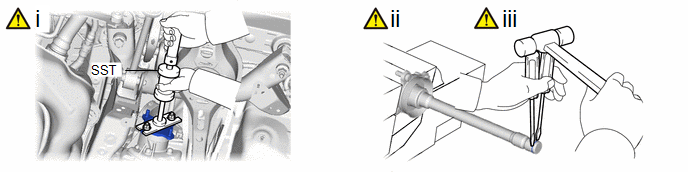
(1) Using SST, remove the differential side gear shaft sub-assembly LH from the rear traction motor with transaxle assembly.
SST: 09520-24010
09520-04010
09520-32040
NOTICE:
Do not damage the differential side gear shaft LH type T oil seal.
(2) Secure the differential side gear shaft sub-assembly LH in a vise between aluminum plates.
NOTICE:
Do not overtighten the vise.
(3) Using 2 screwdrivers and a hammer, remove the snap ring from the differential side gear shaft sub-assembly LH.
NOTICE:
Cover the snap ring with a piece of cloth to prevent it from flying out.
4. REMOVE DIFFERENTIAL SIDE GEAR SHAFT SUB-ASSEMBLY RH
(a) Perform the same procedure as for the LH side.
5. REMOVE DIFFERENTIAL SIDE GEAR SHAFT DUST COVER LH
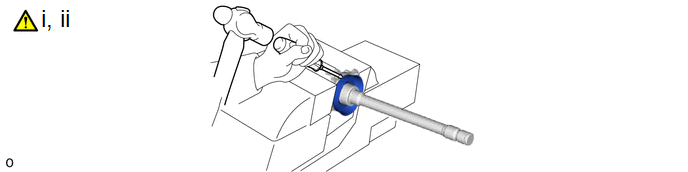
(1) Secure the differential side gear shaft sub-assembly LH in a vise between aluminum plates.
NOTICE:
Do not overtighten the vise.
(2) Using a screwdriver and hammer, remove the differential side gear shaft dust cover LH from the differential side gear shaft sub-assembly LH.
NOTICE:
Do not damage the differential side gear shaft sub-assembly LH.
6. REMOVE DIFFERENTIAL SIDE GEAR SHAFT DUST COVER RH
(a) Perform the same procedure as for the LH side.


