Toyota Corolla Cross: Removal
REMOVAL
CAUTION / NOTICE / HINT
COMPONENTS (REMOVAL)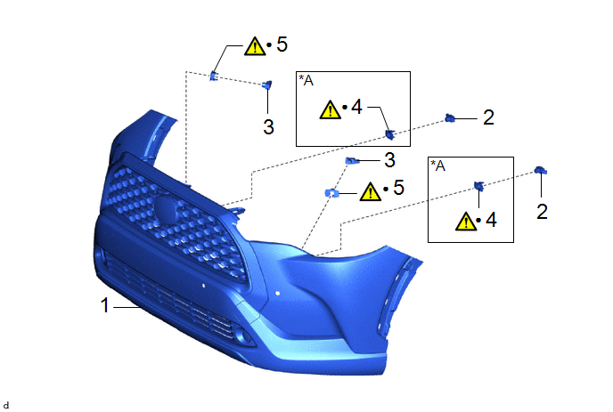
|
Procedure |
Part Name Code |
.png) |
.png) |
.png) |
|
|---|---|---|---|---|---|
|
1 |
FRONT BUMPER ASSEMBLY |
- |
- |
- |
- |
|
2 |
FRONT CENTER ULTRASONIC SENSOR |
89341L |
- |
- |
- |
|
3 |
FRONT CORNER ULTRASONIC SENSOR |
89341K |
- |
- |
- |
|
4 |
FRONT CENTER ULTRASONIC SENSOR RETAINER |
89C48E |
|
- |
- |
|
5 |
FRONT CORNER ULTRASONIC SENSOR RETAINER |
89C48D |
|
- |
- |
|
*A |
except Sport Package |
- |
- |
|
● |
Non-reusable part |
- |
- |
|
Procedure |
Part Name Code |
|
|
|
|
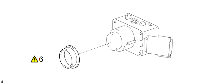
|---|---|---|---|---|---|
|
6 |
ULTRASONIC SENSOR CUSHION SET |
89305 |
|
- |
- |
CAUTION / NOTICE / HINT
The necessary procedures (adjustment, calibration, initialization or registration) that must be performed after parts are removed and installed, or replaced during ultrasonic sensor removal/installation are shown below.
Necessary Procedures After Parts Removed/Installed/Replaced|
Replaced Part or Performed Procedure |
Necessary Procedure |
Effect/Inoperative Function when Necessary Procedure not Performed |
Link |
|---|---|---|---|
|
Ultrasonic sensor |
|
|
|
PROCEDURE
1. REMOVE FRONT BUMPER ASSEMBLY
- except Sport Package:
Click here
.gif)
- for Sport Package:
Click here
2. REMOVE FRONT CENTER ULTRASONIC SENSOR
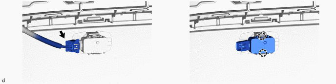
(b) The illustration is for the LH side. The orientation for the RH side is the opposite of the LH side.
3. REMOVE FRONT CORNER ULTRASONIC SENSOR
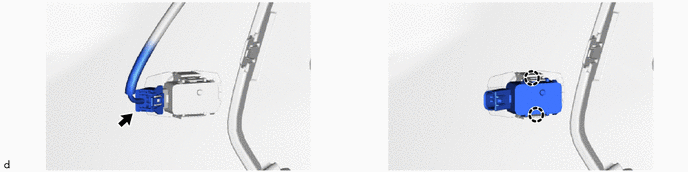
(b) The illustration is for the LH side. The orientation for the RH side is the opposite of the LH side.
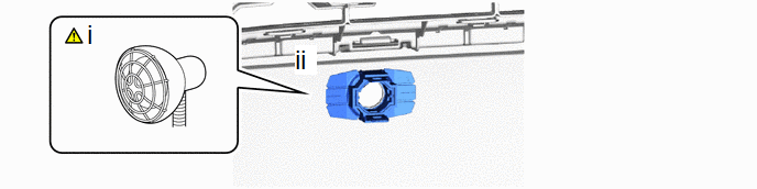
4. REMOVE FRONT CENTER ULTRASONIC SENSOR RETAINER (except Sport Package)
|
|
NOTICE:
|
(1) Heat the adhesive of the front bumper assembly and front center ultrasonic sensor retainer using a heat light.
Standard:
|
Item |
Temperature |
Item |
Temperature |
|---|---|---|---|
|
Front Bumper Assembly |
40 to 50 °C (104 to 122 °F) |
Front Center Ultrasonic Sensor Retainer |
40 to 50 °C (104 to 122 °F) |
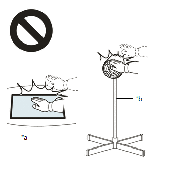
CAUTION:
- Do not touch the heat light and heated parts.
- Touching the heat light may result in burns.
- Touching heated parts for a long time may result in burns.
|
*a |
Heated Part |
|
*b |
Heat Light |
NOTICE:
Do not heat the front bumper assembly and front center ultrasonic sensor retainer excessively.
HINT:
Heat the front bumper assembly and front center ultrasonic sensor retainer using a heat light at the specified temperature for 3 to 5 minutes.
(2) Remove the front center ultrasonic sensor retainer.
(b) The illustration is for the LH side. The orientation for the RH side is the opposite of the LH side.
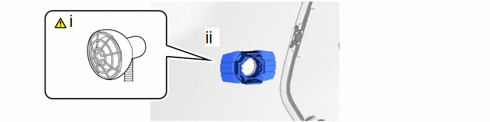
5. REMOVE FRONT CORNER ULTRASONIC SENSOR RETAINER
|
|
NOTICE:
|
(1) Heat the adhesive of the front bumper assembly and front corner ultrasonic sensor retainer using a heat light.
Standard:
|
Item |
Temperature |
Item |
Temperature |
|---|---|---|---|
|
Front Bumper Assembly |
40 to 50 °C (104 to 122 °F) |
Front Corner Ultrasonic Sensor Retainer |
40 to 50 °C (104 to 122 °F) |
CAUTION:
- Do not touch the heat light and heated parts.
- Touching the heat light may result in burns.
- Touching heated parts for a long time may result in burns.
|
*a |
Heated Part |
|
*b |
Heat Light |
NOTICE:
Do not heat the front bumper assembly and front corner ultrasonic sensor retainer excessively.
HINT:
Heat the front bumper assembly and front corner ultrasonic sensor retainer using a heat light at the specified temperature for 3 to 5 minutes.
(2) Remove the front corner ultrasonic sensor retainer.
(b) The illustration is for the LH side. The orientation for the RH side is the opposite of the LH side.
6. REMOVE ULTRASONIC SENSOR CUSHION SET
|
|
NOTICE: Perform this procedure only when replacement of the ultrasonic sensor cushion set is necessary. |