Toyota Corolla Cross: Installation
INSTALLATION
CAUTION / NOTICE / HINT
COMPONENTS (INSTALLATION)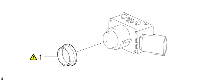
|
Procedure |
Part Name Code |
.png) |
.png) |
.png) |
|
|---|---|---|---|---|---|
|
1 |
ULTRASONIC SENSOR CUSHION SET |
89305 |
|
- |
- |
|
Procedure |
Part Name Code |
|
|
|
|
|---|---|---|---|---|---|
|
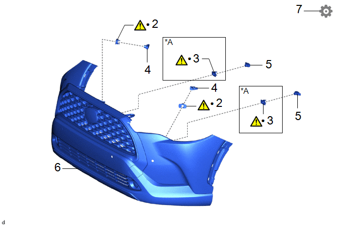
2 |
FRONT CORNER ULTRASONIC SENSOR RETAINER |
89C48D |
|
- |
- |
|
3 |
FRONT CENTER ULTRASONIC SENSOR RETAINER |
89C48E |
|
- |
- |
|
4 |
FRONT CORNER ULTRASONIC SENSOR |
89341K |
- |
- |
- |
|
5 |
FRONT CENTER ULTRASONIC SENSOR |
89341L |
- |
- |
- |
|
6 |
FRONT BUMPER ASSEMBLY |
- |
- |
- |
- |
|
7 |
PERFORM CALIBRATION |
- |
- |
- |
|
|
*A |
except Sport Package |
- |
- |
|
● |
Non-reusable part |
- |
- |
PROCEDURE
1. INSTALL ULTRASONIC SENSOR CUSHION SET
|
|
NOTICE: Perform this procedure only when replacement of the ultrasonic sensor cushion set is necessary. |
2. INSTALL FRONT CORNER ULTRASONIC SENSOR RETAINER
|
|
NOTICE: Perform this procedure only when replacement of the front corner ultrasonic sensor retainer is necessary. |
|
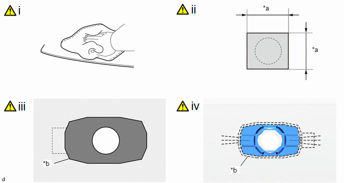
*a |
30 mm (1.18 in.) |
*b |
Scribed Line |
 |
Primer Application |
- |
- |
(1) Clean the front bumper assembly surface:
1. When reusing the front bumper assembly, remove remaining double-sided tape from the front bumper assembly.
2. Using a heat light, heat the front bumper assembly surface.
Heating Temperature:
|
Item |
Temperature |
Item |
Temperature |
|---|---|---|---|
|
Front Bumper Assembly |
40 to 50 °C (104 to 122 °F) |
- |
- |
CAUTION:
- Do not touch the heat light and heated parts.
- Touching the heat light may result in burns.
- Touching heated parts for a long time may result in burns.
.png)
|
*a |
Heated Part |
|
*b |
Heat Light |
NOTICE:
Do not heat the front bumper assembly excessively.
3. Remove any remaining double-sided tape from the front bumper assembly and wipe off any tape adhesive residue with cleaner.
4. Clean the installation area surface.
NOTICE:
- Installing the front corner ultrasonic sensor retainer with some double-sided tape remaining may cause poor adhesion. Perform this procedure until the tape is sufficiently removed.
- Make sure to use a cloth when removing. Using a screwdriver, etc., may cause damage and poor adhesion.
(2) Cover the sensor installation hole from the outside of the front bumper assembly with a 30 mm (1.18 in.) square piece of tape.
(3) Primer application:
1. Apply primer to the front bumper assembly on the installation area of the front corner ultrasonic sensor retainer using a brush or felt.
NOTICE:
- Replace the brush or felt if it is dirty or has become hardened.
- Keep any painted surface free from primer.
- If the primer contacts a painted surface, it may leave light primer marks. Therefore, use protective tape when using liquid primer.
- Do not touch surfaces to which primer has been applied until the front corner ultrasonic sensor retainer has been attached.
2. Let the primer dry sufficiently.
NOTICE:
Do not touch applied surfaces until the primer is dry.
Recommended drying time:
10 Minutes or more (at 23°C (73°F))
3. Confirm that the primer has completely dried by touching the front bumper assembly. Then remove the tape.
(4) Install a new front corner ultrasonic sensor retainer:
1. Remove the peeling paper of the front corner ultrasonic sensor retainer trying not to touch the adhesional surface.
NOTICE:
After removing the peeling paper, do not touch the surface of the tape with your fingers or cotton work gloves.
2. Using a heat light, heat the front bumper assembly and front corner ultrasonic sensor retainer.
Heating Temperature:
|
Item |
Temperature |
Item |
Temperature |
|---|---|---|---|
|
Front Bumper Assembly |
40 to 50 °C (104 to 122 °F) |
Front Corner Ultrasonic Sensor Retainer |
40 to 50 °C (104 to 122 °F) |
CAUTION:
- Do not touch the heat light and heated parts.
- Touching the heat light may result in burns.
- Touching heated parts for a long time may result in burns.
NOTICE:
Do not heat the front bumper assembly excessively.
3. Install the front corner ultrasonic sensor retainer in the position shown in the illustration.
NOTICE:
The application strength of the front corner ultrasonic sensor retainer will weaken if reapplied. If reapplication is necessary, be sure to replace it with a new one.
HINT:
Apply pressure so that it does not lift up from the front bumper assembly.
(b) The orientation for the RH side is the opposite of the LH side.
3. INSTALL FRONT CENTER ULTRASONIC SENSOR RETAINER (except Sport Package)
|
|
NOTICE: Perform this procedure only when replacement of the front center ultrasonic sensor retainer is necessary. |
|
*a |
30 mm (1.18 in.) |
*b |
Scribed Line |
|
|
Primer Application |
- |
- |
(1) Clean the front bumper assembly surface:
1. When reusing the front bumper assembly, remove remaining double-sided tape from the front bumper assembly.
2. Using a heat light, heat the front bumper assembly surface.
Heating Temperature:
|
Item |
Temperature |
Item |
Temperature |
|---|---|---|---|
|
Front Bumper Assembly |
40 to 50 °C (104 to 122 °F) |
- |
- |
CAUTION:
- Do not touch the heat light and heated parts.
- Touching the heat light may result in burns.
- Touching heated parts for a long time may result in burns.
|
*a |
Heated Part |
|
*b |
Heat Light |
NOTICE:
Do not heat the front bumper assembly excessively.
3. Remove any remaining double-sided tape from the front bumper assembly and wipe off any tape adhesive residue with cleaner.
4. Clean the installation area surface.
NOTICE:
- Installing the front center ultrasonic sensor retainer with some double-sided tape remaining may cause poor adhesion. Perform this procedure until the tape is sufficiently removed.
- Make sure to use a cloth when removing. Using a screwdriver, etc., may cause damage and poor adhesion.
(2) Cover the sensor installation hole from the outside of the front bumper assembly with a 30 mm (1.18 in.) square piece of tape.
(3) Primer application:
1. Apply primer to the front bumper assembly on the installation area of the front center ultrasonic sensor retainer using a brush or felt.
NOTICE:
- Replace the brush or felt if it is dirty or has become hardened.
- Keep any painted surface free from primer.
- If the primer contacts a painted surface, it may leave light primer marks. Therefore, use protective tape when using liquid primer.
- Do not touch surfaces to which primer has been applied until the front center ultrasonic sensor retainer has been attached.
2. Let the primer dry sufficiently.
NOTICE:
Do not touch applied surfaces until the primer is dry.
Recommended drying time:
10 Minutes or more (at 23°C (73°F))
3. Confirm that the primer has completely dried by touching the front bumper assembly. Then remove the tape.
(4) Install a new front center ultrasonic sensor retainer:
1. Remove the peeling paper of the front center ultrasonic sensor retainer trying not to touch the adhesional surface.
NOTICE:
After removing the peeling paper, do not touch the surface of the tape with your fingers or cotton work gloves.
2. Using a heat light, heat the front bumper assembly and front center ultrasonic sensor retainer.
Heating Temperature:
|
Item |
Temperature |
Item |
Temperature |
|---|---|---|---|
|
Front Bumper Assembly |
40 to 50 °C (104 to 122 °F) |
Front Center Ultrasonic Sensor Retainer |
40 to 50 °C (104 to 122 °F) |
CAUTION:
- Do not touch the heat light and heated parts.
- Touching the heat light may result in burns.
- Touching heated parts for a long time may result in burns.
NOTICE:
Do not heat the front bumper assembly excessively.
3. Install the front center ultrasonic sensor retainer in the position shown in the illustration.
NOTICE:
The application strength of the front center ultrasonic sensor retainer will weaken if reapplied. If reapplication is necessary, be sure to replace it with a new one.
HINT:
Apply pressure so that it does not lift up from the front bumper assembly.
(b) The orientation for the RH side is the opposite of the LH side.
4. INSTALL FRONT CORNER ULTRASONIC SENSOR
5. INSTALL FRONT CENTER ULTRASONIC SENSOR
6. INSTALL FRONT BUMPER ASSEMBLY
- except Sport Package:
Click here
.gif)
- for Sport Package:
Click here
7. PERFORM CALIBRATION
Click here


