Toyota Corolla Cross: Inspection
INSPECTION
PROCEDURE
1. INSPECT FRONT CENTER ULTRASONIC SENSOR (for LH Side)
(a) Check the resistance.
|
(1) Measure the resistance according to the value(s) in the
table below.
Standard Resistance:
|
Tester Connection
|
Condition
|
Specified Condition
|
|
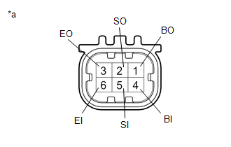
4 (BI) - 6 (EI)
|
Always
|
10 kΩ or higher
|
|
4 (BI) - 1 (BO)
|
Always
|
Below 1 Ω
|
|
5 (SI) - 2 (SO)
|
Always
|
Below 30 Ω
|
|
6 (EI) - 3 (EO)
|
Always
|
Below 1 Ω
|
If the result is not as specified, replace the front center
ultrasonic sensor.
|
 |
|
*a
|
Component without harness connected (Front
Center Ultrasonic Sensor)
|
|
|
2. INSPECT FRONT CENTER ULTRASONIC SENSOR (for RH Side)
(a) Check the resistance.
|
(1) Measure the resistance according to the value(s) in the
table below.
Standard Resistance:
|
Tester Connection
|
Condition
|
Specified Condition
|
|
4 (BI) - 6 (EI)
|
Always
|
10 kΩ or higher
|
|
4 (BI) - 1 (BO)
|
Always
|
Below 1 Ω
|
|
5 (SI) - 2 (SO)
|
Always
|
Below 30 Ω
|
|
6 (EI) - 3 (EO)
|
Always
|
Below 1 Ω
|
If the result is not as specified, replace the front center
ultrasonic sensor.
|
|
|
|
*a
|
Component without harness connected (Front
Center Ultrasonic Sensor)
|
|
|
3. INSPECT FRONT CORNER ULTRASONIC SENSOR (for LH Side)
(a) Check the resistance.
|
(1) Measure the resistance according to the value(s) in the
table below.
Standard Resistance:
|
Tester Connection
|
Condition
|
Specified Condition
|
|
4 (BI) - 6 (EI)
|
Always
|
10 kΩ or higher
|
|
4 (BI) - 1 (BO)
|
Always
|
Below 1 Ω
|
|
5 (SI) - 2 (SO)
|
Always
|
Below 30 Ω
|
|
6 (EI) - 3 (EO)
|
Always
|
Below 1 Ω
|
If the result is not as specified, replace the front corner
ultrasonic sensor.
|
|
|
|
*a
|
Component without harness connected (Front
Corner Ultrasonic Sensor)
|
|
|
4. INSPECT FRONT CORNER ULTRASONIC SENSOR (for RH Side)
(a) Check the resistance.
|
(1) Measure the resistance according to the value(s) in the
table below.
Standard Resistance:
|
Tester Connection
|
Condition
|
Specified Condition
|
|
4 (BI) - 6 (EI)
|
Always
|
10 kΩ or higher
|
|
4 (BI) - 1 (BO)
|
Always
|
Below 1 Ω
|
|
5 (SI) - 2 (SO)
|
Always
|
Below 30 Ω
|
|
6 (EI) - 3 (EO)
|
Always
|
Below 1 Ω
|
If the result is not as specified, replace the front corner
ultrasonic sensor.
|
|
|
|
*a
|
Component without harness connected (Front
Corner Ultrasonic Sensor)
|
|
|
READ NEXT:
INSTALLATION
CAUTION / NOTICE / HINT
COMPONENTS (INSTALLATION)
Procedure
Part Name Code
1
ULTRASONIC SENSOR CUSHION SET
REMOVAL
CAUTION / NOTICE / HINT
COMPONENTS (REMOVAL)
Procedure
Part Name Code
1
REAR BUMPER ASSEMBLY
-
SEE MORE:
ON-VEHICLE INSPECTION PROCEDURE
1. INSPECT SPEEDOMETER
NOTICE:
The combination meter assembly receives the vehicle speed signal from the skid control ECU (brake actuator assembly) via CAN communication. Therefore, perform the following inspection referring to values on the Data List of the s
PARTS LOCATION
ILLUSTRATION
*1
TIRE PRESSURE WARNING VALVE AND TRANSMITTER
*2
TIRE PRESSURE WARNING ECU AND RECEIVER
ILLUSTRATION
*A
w/o Stop and Start System
-
-
*1
C


