Toyota Corolla Cross: Removal
REMOVAL
CAUTION / NOTICE / HINT
COMPONENTS (REMOVAL)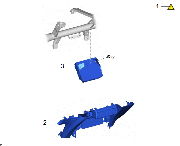
|
Procedure |
Part Name Code |
.png) |
.png) |
.png) |
|
|---|---|---|---|---|---|
|
1 |
PRECAUTION |
- |
|
- |
- |
|
2 |
LOWER CENTER INSTRUMENT PANEL FINISH PANEL |
55434F |
- |
- |
- |
|
3 |
TELEPHONE TRANSCEIVER WITH BRACKET |
- |
- |
- |
- |
|
Procedure |
Part Name Code |
|
|
|
|
|---|---|---|---|---|---|
|
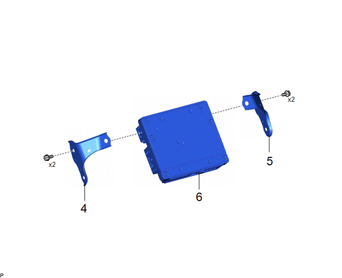
4 |
NO. 2 TELEPHONE BRACKET |
86719B |
- |
- |
- |
|
5 |
NO. 1 TELEPHONE BRACKET |
86719A |
- |
- |
- |
|
6 |
TELEMATICS TRANSCEIVER |
86741A |
- |
- |
- |
CAUTION / NOTICE / HINT
The necessary procedures (adjustment, calibration, initialization, or registration) that must be performed after parts are removed and installed, or replaced during telematics transceiver removal/installation are shown below.
Necessary Procedure After Parts Removed/Installed/Replaced|
Replaced Part or Performed Procedure |
Necessary Procedure |
Effect/Inoperative Function when Necessary Procedure not Performed |
Link |
|---|---|---|---|
|
DCM (Telematics transceiver) |
DCM activation |
Safety connect system |
|
|
Code registration |
Telematics system |
PROCEDURE
1. PRECAUTION
Click here .gif)
2. REMOVE LOWER CENTER INSTRUMENT PANEL FINISH PANEL
Click here
3. REMOVE TELEPHONE TRANSCEIVER WITH BRACKET

(1) Disconnect each connector.
(2) Remove the 2 nuts and telephone transceiver with bracket.
4. REMOVE NO. 2 TELEPHONE BRACKET

5. REMOVE NO. 1 TELEPHONE BRACKET

6. REMOVE TELEMATICS TRANSCEIVER


