Toyota Corolla Cross: Mayday Battery
Removal
REMOVAL
CAUTION / NOTICE / HINT
COMPONENTS (REMOVAL)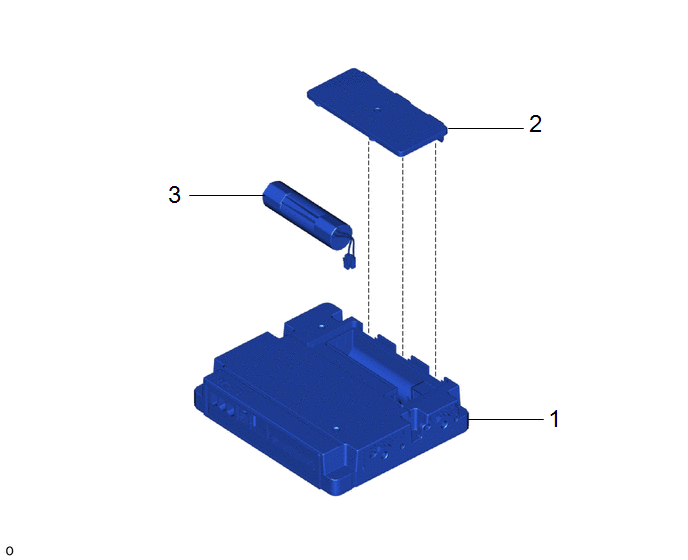
|
Procedure |
Part Name Code |
.png) |
.png) |
.png) |
|
|---|---|---|---|---|---|
|
1 |
TELEMATICS TRANSCEIVER |
86741A |
- |
- |
- |
|
2 |
TRANSCEIVER COVER |
86742 |
- |
- |
- |
|
3 |
MOBILEPHONE BATTERY |
86745 |
- |
- |
- |
CAUTION / NOTICE / HINT
The necessary procedures (adjustment, calibration, initialization, or registration) that must be performed after parts are removed and installed, or replaced during mobile phone battery removal/installation are shown below.
Necessary Procedure After Parts Removed/Installed/Replaced|
Replaced Part or Performed Procedure |
Necessary Procedure |
Effect/Inoperative Function when Necessary Procedure not Performed |
Link |
|---|---|---|---|
|
Mobilephone battery |
Reset mobilephone battery condition |
Safety connect system |
|
PROCEDURE
1. REMOVE TELEMATICS TRANSCEIVER
Click here .gif)
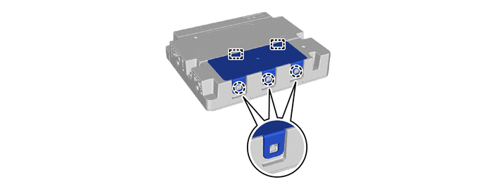
2. REMOVE TRANSCEIVER COVER
3. REMOVE MOBILEPHONE BATTERY
NOTICE:
Do not reuse dropped or damaged parts.
(a) Remove the mobilephone battery as shown in the illustration.
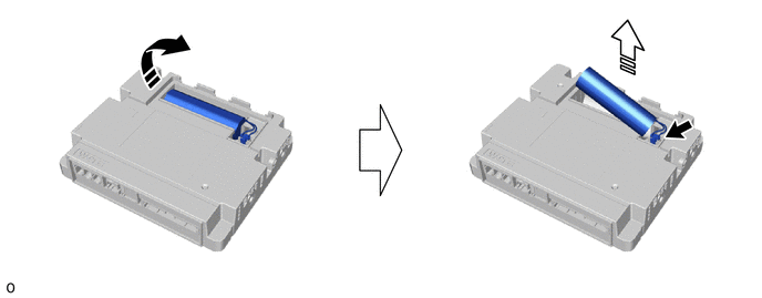
.png) |
Remove in this Direction (1) |
.png) |
Remove in this Direction (2) |
(b) Disconnect the connector.
Installation
INSTALLATION
CAUTION / NOTICE / HINT
COMPONENTS (INSTALLATION)
|
Procedure |
Part Name Code |
.png) |
.png) |
.png) |
|
|---|---|---|---|---|---|
|
1 |
MOBILEPHONE BATTERY |
86725 |
- |
- |
- |
|
2 |
TRANSCEIVER COVER |
86742 |
- |
- |
- |
|
3 |
TELEMATICS TRANSCEIVER |
86741A |
- |
- |
- |
PROCEDURE
1. INSTALL MOBILEPHONE BATTERY
(a) Connect the connector to install a new mobilephone battery as shown in the illustration.
NOTICE:
Check that the connector is securely connected.
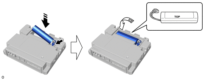
.png) |
Install in this Direction (1) |
.png) |
Install in this Direction (2) |
2. INSTALL TRANSCEIVER COVER
3. INSTALL TELEMATICS TRANSCEIVER
Click here .gif)
4. PERFORM INITIALIZATION
Click here


