Toyota Corolla Cross: Relay
On-vehicle Inspection
ON-VEHICLE INSPECTION
PROCEDURE
1. INSPECT NO. 1 ELECTRONIC FUEL INJECTION MAIN RELAY (EFI-MAIN NO. 1)
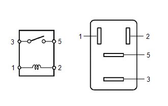
| (a) Measure the resistance according to the value(s) in the table below.
Standard Resistance: |
Tester Connection | Condition |
Specified Condition | |
3 - 5 | Auxiliary battery voltage not applied between terminals 1 and 2 |
10 kΩ or higher | |
Auxiliary battery voltage applied between terminals 1 and 2 |
Below 1 Ω | If the result is not as specified, replace the No. 1 electronic fuel injection main relay (EFI-MAIN NO. 1). |
|
2. INSPECT NO. 3 ELECTRONIC FUEL INJECTION MAIN RELAY (EFI-MAIN NO. 3)
| (a) Measure the resistance according to the value(s) in the table below.
Standard Resistance: |
Tester Connection | Condition |
Specified Condition | |
3 - 5 | Auxiliary battery voltage not applied between terminals 1 and 2 |
10 kΩ or higher | |
Auxiliary battery voltage applied between terminals 1 and 2 |
Below 1 Ω | If the result is not as specified, replace the No. 3 electronic fuel injection main relay (EFI-MAIN NO. 3). |
|
3. INSPECT INJECTOR RELAY (D INJ)
| (a) Measure the resistance according to the value(s) in the table below.
Standard Resistance: |
Tester Connection | Condition |
Specified Condition | |
3 - 5 | Auxiliary battery voltage not applied between terminals 1 and 2 |
10 kΩ or higher | |
Auxiliary battery voltage applied between terminals 1 and 2 |
Below 1 Ω | If the result is not as specified, replace the injector relay (D INJ). |
|
4. INSPECT VVT RELAY (VVT)
| (a) Measure the resistance according to the value(s) in the table below.
Standard Resistance: |
Tester Connection | Condition |
Specified Condition | |
3 - 5 | Auxiliary battery voltage not applied between terminals 1 and 2 |
10 kΩ or higher | |
Auxiliary battery voltage applied between terminals 1 and 2 |
Below 1 Ω | If the result is not as specified, replace the VVT relay (VVT). |
|
READ NEXT:
PRECAUTION WHEN USING GTS
CAUTION:
Strictly obey all traffic rules and regulations.
Do not drive the vehicle with the GTS cable contacting the pedals, shift lever or steering wheel.
Dr
DEFINITION OF TERMS
Term Definition
Monitor Description Description of what the ECM monitors and how it detects malfunctions (monitoring purpose and details).
Related DTCs
SEE MORE:
OPERATION CHECK CHECK SRS WARNING LIGHT (a) Primary check
(1) Turn the ignition switch to ON and check that the SRS warning light turns on.
(2) Turn the ignition switch off. Wait for at least 2 seconds, then turn the ignition switch to ON. The SRS warning light comes on for approximately 6 seco
INSTALLATION
CAUTION / NOTICE / HINT
COMPONENTS (INSTALLATION)
Procedure
Part Name Code
1
AUXILIARY BATTERY
-
-
-
-
2
BATTERY CLAMP
7448