Toyota Corolla Cross: Reassembly
REASSEMBLY
CAUTION / NOTICE / HINT
COMPONENTS (REASSEMBLY)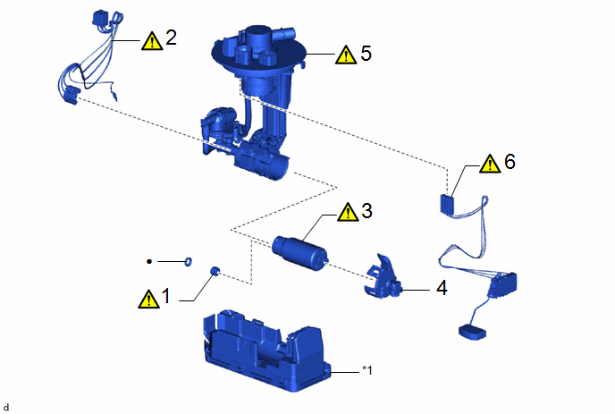
|
Procedure | Part Name Code |
.png) |
.png) |
 |
|---|---|---|---|---|---|
|
1 | FUEL PUMP SPACER |
23225A |
|
- | - |
|
2 | FUEL PUMP HARNESS |
77785 |
|
- | - |
|
3 | FUEL PUMP |
23221 |
|
- | - |
|
4 | NO. 2 FUEL SUCTION SUPPORT |
77175 | - |
- | - |
|
5 | FUEL SUCTION PLATE SUB-ASSEMBLY |
77024A |
|
- | - |
|
6 | FUEL SENDER GAUGE ASSEMBLY |
83320 |
|
- | - |
.gif)
|
*1 | FUEL SUB-TANK SUB-ASSEMBLY |
- | - |
|
● | Non-reusable part |
- | - |
PROCEDURE
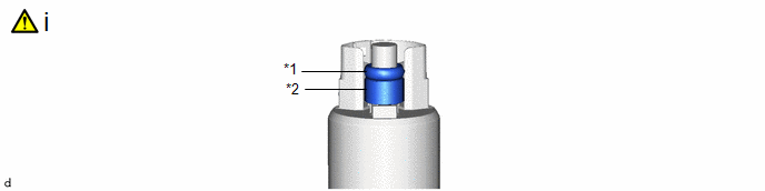
1. INSTALL FUEL PUMP SPACER
|
*1 | O-ring |
*2 | Fuel Pump Spacer |
(1) Apply gasoline to a new O-ring. Then install the O-ring and fuel pump spacer to the fuel pump.
2. INSTALL FUEL PUMP HARNESS
|
|
NOTICE: Do not damage the wire harness. |
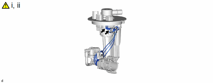
(1) Connect the 2 fuel pump harness connectors and install the fuel pump harness to the fuel suction plate sub-assembly.
NOTICE:
When disengaging each wire harness from the clamp, disengage one wire at a time.
(2) Engage the clamp.
3. INSTALL FUEL PUMP
|
|
NOTICE: Perform "Inspection After Repair" after replacing the fuel pump. Click here |

(1) Install the fuel pump to the fuel tube supporter.
NOTICE:
Make sure that the O-ring is not cut or pinched during installation.
4. INSTALL NO. 2 FUEL SUCTION SUPPORT
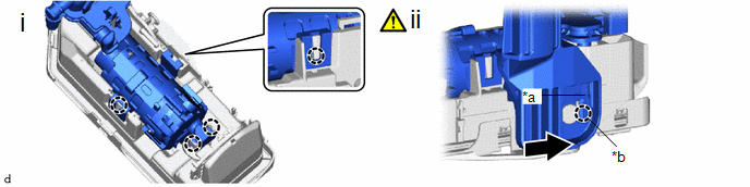
5. INSTALL FUEL SUCTION PLATE SUB-ASSEMBLY
|
*a | Protrusion |
*b | Installation Hole |
.png) |
Slide | - |
- |
(1) Engage the 4 claws to install the fuel suction plate sub-assembly to the fuel sub-tank sub-assembly.
(2) Align the protrusion of the fuel sub-tank sub-assembly with the installation hole of the fuel suction plate sub-assembly and then slide the fuel suction plate sub-assembly to install the fuel sub-tank sub-assembly.
6. INSTALL FUEL SENDER GAUGE ASSEMBLY
|
|
Click here |


