Toyota Corolla Cross: Reassembly
REASSEMBLY
CAUTION / NOTICE / HINT
|
Procedure | Part Name Code |
.png) |
.png) |
 |
|---|---|---|---|---|---|
|
1 | WIRE HARNESS CLAMP BRACKET |
- | - |
- | - |
|
2 | FUEL HOSE BRACKET |
23881B | - |
- | - |
|
3 | HV AIR CONDITIONING WIRE |
821H2 |
|
- | - |
|
4 | NO. 3 ENGINE WIRE |
82123 |
|
- | - |
|
5 | NO. 2 INVERTER BRACKET |
G9215 |
|
- | - |
|
6 | NO. 1 INVERTER BRACKET |
G9214 |
|
- | - |
.gif)
.png) |
Tightening torque for "Major areas involving basic vehicle performance such as moving/turning/stopping" : N*m (kgf*cm, ft.*lbf) |
.png) |
N*m (kgf*cm, ft.*lbf): Specified torque |
PROCEDURE
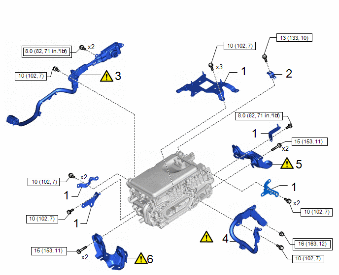
1. INSTALL WIRE HARNESS CLAMP BRACKET
Torque:
Bolt A :
10 N·m {102 kgf·cm, 7 ft·lbf}
Bolt B :
8.0 N·m {82 kgf·cm, 71 in·lbf}
2. INSTALL FUEL HOSE BRACKET
Torque:
13 N·m {133 kgf·cm, 10 ft·lbf}
3. INSTALL HV AIR CONDITIONING WIRE
|
|
CAUTION: Be sure to wear insulated gloves. NOTICE:
|
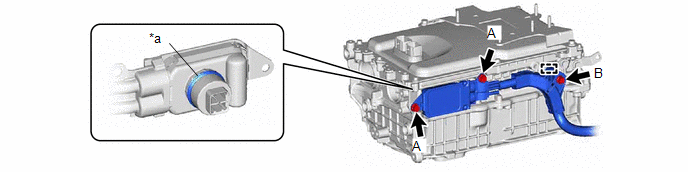
|
*a | Waterproof Seal |
- | - |
Torque:
Bolt A :
8.0 N·m {82 kgf·cm, 71 in·lbf}
Bolt B :
10 N·m {102 kgf·cm, 7 ft·lbf}
4. INSTALL NO. 3 ENGINE WIRE
|
|
CAUTION: Be sure to wear insulated gloves. NOTICE:
|
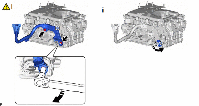
(1) Engage the clamp and connect the engine wire to the inverter with converter assembly with bolt and nut.
Torque:
Bolt :
10 N·m {102 kgf·cm, 7 ft·lbf}
Nut :
16 N·m {163 kgf·cm, 12 ft·lbf}
NOTICE:
- Move the tool in the downward direction to tighten the nut as shown in the illustration.
- To avoid damaging the threads, be sure to perform the procedure by hand.
(2) Engage the 2 claws.
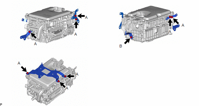
5. INSTALL NO. 2 INVERTER BRACKET
|
|
NOTICE: Make sure to support the inverter with converter assembly at the positions shown in the illustration, otherwise it may be damaged. .png)
|
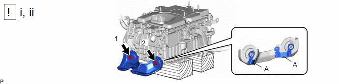
(1) Set the inverter with converter assembly on wooden blocks.
(2) Temporarily install the No. 2 inverter bracket to the inverter with converter assembly with the 2 bolts.
NOTICE:
Do not touch portion (A) of the No. 2 inverter bracket.
(3) Fully tighten the 2 bolts in the order shown in the illustration.
Torque:
15 N·m {153 kgf·cm, 11 ft·lbf}
6. INSTALL NO. 1 INVERTER BRACKET
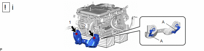
(1) Temporarily install the No. 1 inverter bracket to the inverter with converter assembly with the 2 bolts.
NOTICE:
Do not touch portion (A) of the No. 1 inverter bracket.
(2) Fully tighten the 2 bolts in the order shown in the illustration.
Torque:
15 N·m {153 kgf·cm, 11 ft·lbf}


