Toyota Corolla Cross Owners & Service Manuals

Toyota Corolla Cross: Reassembly

REASSEMBLY

CAUTION / NOTICE / HINT

COMPONENTS (REASSEMBLY)
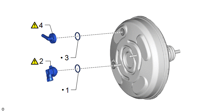
Procedure

Part Name Code

1

VACUUM SENSOR GROMMET

89420K

-

-

-

2

VACUUM SENSOR ASSEMBLY

89420H

-

-

3

CHECK VALVE GROMMET

-

-

-

-

4

BRAKE VACUUM CHECK VALVE ASSEMBLY

44730


-

Non-reusable part

-

-

PROCEDURE

1. INSTALL VACUUM SENSOR GROMMET

2. INSTALL VACUUM SENSOR ASSEMBLY

*a

30° +/- 6°

-

-

Up

-

-

(1) Install the vacuum sensor assembly to the brake booster assembly as shown in the illustration.

3. INSTALL CHECK VALVE GROMMET

4. INSTALL BRAKE VACUUM CHECK VALVE ASSEMBLY

*a

45° +/- 20°

-

-

Up

-

-

(1) Install the brake vacuum check valve assembly to the brake booster assembly.

    READ NEXT:

     Installation

    INSTALLATION CAUTION / NOTICE / HINT COMPONENTS (INSTALLATION) Procedure Part Name Code 1 BRAKE BOOSTER GASKET

     Brake Booster (for Hev Model)

     Removal

    REMOVAL CAUTION / NOTICE / HINT COMPONENTS (REMOVAL) Procedure Part Name Code 1 PRECAUTION -

    SEE MORE:

     Inspection

    INSPECTION PROCEDURE 1. INSPECT FRONT NO. 1 SPEAKER ASSEMBLY LH (w/o Stereo Component Amplifier) (a) With the front No. 1 speaker assembly LH installed, check that there is no looseness or other abnormalities. (b) Check that there is no foreign matter in the front No. 1 speaker assembly LH,

     HO2S Heater Control Circuit Bank 1 Sensor 2 Circuit Short to Battery (P003612,P003613,P102A9E)

    DESCRIPTION The air fuel ratio sensor (sensor 2) generates current that corresponds to the actual air fuel ratio. This sensor current is used to provide the ECM with feedback so that it can control the air fuel ratio. The ECM determines the deviation from the stoichiometric air fuel ratio level, and

    © 2020-2024 Copyright www.tcorollacross.com