Toyota Corolla Cross: Push Switch / Key Unlock Warning Switch Malfunction (B2780)
DESCRIPTION
This DTC is stored if the transponder key ECU assembly does not detect that the unlock warning switch assembly is on even when the ignition switch is ON.
|
DTC No. | Detection Item |
DTC Detection Condition | Trouble Area |
Note |
|---|---|---|---|---|
| B2780 |
Push Switch / Key Unlock Warning Switch Malfunction |
The unlock warning switch assembly is not detected as being on when the ignition switch is ON (1 trip detection logic*). |
| DTC Output Confirmation Operation:
|
- *: Only output while a malfunction is present.
|
Vehicle Condition when Malfunction Detected |
Fail-safe Operation when Malfunction Detected |
|---|---|
|
Engine cannot be started |
- |
|
DTC No. | Data List and Active Test |
|---|---|
|
B2780 | Key SW |
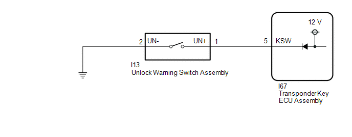
WIRING DIAGRAM
CAUTION / NOTICE / HINT
NOTICE:
- If the transponder key ECU assembly is replaced, refer to Registration.
Click here
.gif)
- After repair, confirm that no DTCs are output by performing "DTC Output Confirmation Operation".
PROCEDURE
|
1. | INSPECT UNLOCK WARNING SWITCH ASSEMBLY |
Click here
| NG | .gif) | REPLACE UNLOCK WARNING SWITCH ASSEMBLY |
|
.gif)
| 2. |
CHECK HARNESS AND CONNECTOR (UNLOCK WARNING SWITCH ASSEMBLY - TRANSPONDER KEY ECU ASSEMBLY - BODY GROUND) |
(a) Disconnect the I67 transponder key ECU assembly connector.
(b) Measure the resistance according to the value(s) in the table below.
Standard Resistance:
|
Tester Connection | Condition |
Specified Condition |
|---|---|---|
|
I13-1 (UN+) - I67-5 (KSW) |
Always | Below 1 Ω |
|
I13-2 (UN-) - Body ground |
Always | Below 1 Ω |
|
I13-1 (UN+) or I67-5 (KSW) - Other terminals and body ground |
Always | 10 kΩ or higher |
| OK | | REPLACE TRANSPONDER KEY ECU ASSEMBLY
|
| NG | | REPAIR OR REPLACE HARNESS OR CONNECTOR |


