Toyota Corolla Cross: Parts Location
PARTS LOCATION
ILLUSTRATION
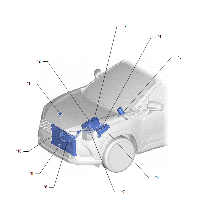
|
*1 | AIR CONDITIONER PRESSURE SENSOR |
*2 | HV AIR CONDITIONING WIRE |
|
*3 | INVERTER WITH CONVERTER ASSEMBLY |
*4 | ECM |
|
*5 | POWER STEERING ECU ASSEMBLY |
*6 | NO. 1 ENGINE ROOM RELAY BLOCK ASSEMBLY - ECU-IGP NO. 3 FUSE - HTR FUSE |
|
*7 | BATTERY STATE SENSOR ASSEMBLY |
*8 | COMPRESSOR WITH MOTOR ASSEMBLY |
|
*9 | THERMISTOR ASSEMBLY |
*10 | COOLER CONDENSER ASSEMBLY |
ILLUSTRATION
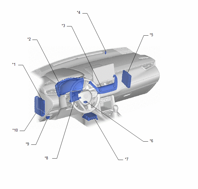
|
*1 | MAIN BODY ECU (MULTIPLEX NETWORK BODY ECU) |
*2 | COMBINATION METER ASSEMBLY |
|
*3 | AIR CONDITIONING CONTROL ASSEMBLY |
*4 | AUTOMATIC LIGHT CONTROL SENSOR |
|
*5 | HYBRID VEHICLE CONTROL ECU |
*6 | COOLER THERMISTOR (ROOM TEMPERATURE SENSOR) |
|
*7 | AIRBAG ECU ASSEMBLY |
*8 | AIR CONDITIONING AMPLIFIER ASSEMBLY |
|
*9 | DLC3 |
*10 | POWER DISTRIBUTION BOX ASSEMBLY - ECU-B NO. 2 FUSE - PANEL FUSE |
ILLUSTRATION
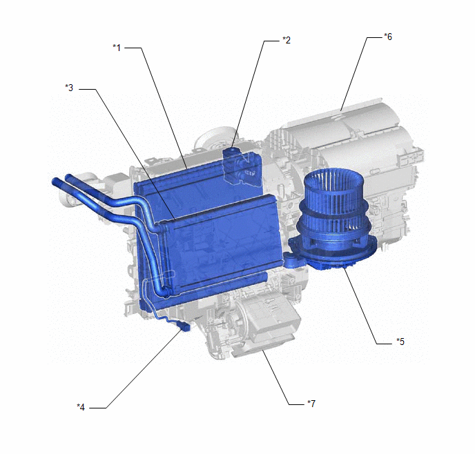
|
*1 | NO. 1 COOLER EVAPORATOR SUB-ASSEMBLY |
*2 | COOLER EXPANSION VALVE |
|
*3 | HEATER RADIATOR UNIT SUB-ASSEMBLY |
*4 | NO. 1 COOLER THERMISTOR |
|
*5 | BLOWER MOTOR WITH FAN SUB-ASSEMBLY |
*6 | BLOWER ASSEMBLY |
|
*7 | AIR CONDITIONING RADIATOR ASSEMBLY |
- | - |
ILLUSTRATION
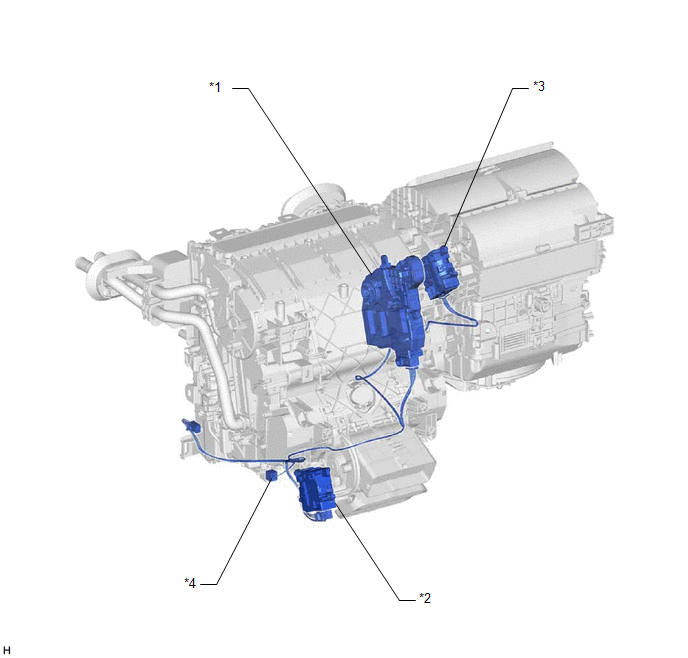
|
*1 | NO. 1 AIR CONDITIONING RADIATOR DAMPER SERVO SUB-ASSEMBLY |
*2 | NO. 2 AIR CONDITIONING RADIATOR DAMPER SERVO SUB-ASSEMBLY |
|
*3 | NO. 1 BLOWER DAMPER SERVO SUB-ASSEMBLY |
*4 | AIR CONDITIONING HARNESS ASSEMBLY |


