Toyota Corolla Cross: Parts Location
PARTS LOCATION
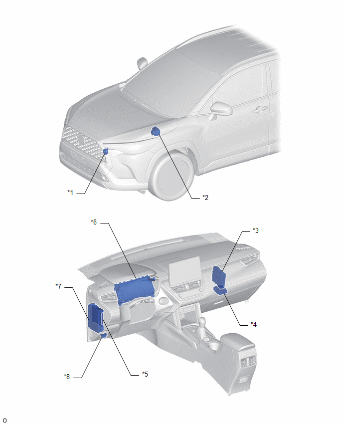
ILLUSTRATION
|
*1 | VEHICLE APPROACHING SPEAKER ASSEMBLY |
*2 | SKID CONTROL ECU (BRAKE ACTUATOR ASSEMBLY) |
|
*3 | HYBRID VEHICLE CONTROL ECU |
*4 | VEHICLE APPROACHING SPEAKER CONTROLLER |
|
*5 | MAIN BODY ECU (MULTIPLEX NETWORK BODY ECU) |
*6 | COMBINATION METER ASSEMBLY |
|
*7 | POWER DISTRIBUTION BOX ASSEMBLY
- ECU-IG1 NO. 2 FUSE |
*8 | DLC3 |
READ NEXT:
SYSTEM DESCRIPTION ACOUSTIC VEHICLE ALERTING SYSTEM
(a) When the vehicle is being driven quietly using the motor only, the acoustic vehicle alerting system outputs a warning sound from the vehicle ap
CAUTION / NOTICE / HINT
HINT:
Use the following procedure to troubleshoot the acoustic vehicle alerting system.
*: Use the GTS.
PROCEDURE
1. VEHICLE BROUGHT TO WORKSHOP
N
SEE MORE:
1. Remove any dirt or foreign
matter from the wheel contact
surface.
If foreign matter is on the wheel
contact surface, the wheel nuts
may loosen while the vehicle is in motion, causing the tire to come off.
2. Install the tire and loosely
tighten each wheel nut by
hand by approximately the
same a
REMOVAL CAUTION / NOTICE / HINT COMPONENTS (REMOVAL)
Procedure Part Name Code
1 FUEL SUCTION TUBE WITH PUMP AND GAUGE ASSEMBLY
77020A -
- -
2 DRAIN FUEL
-
- -
3 TAIL EXHAUST PIPE ASSEMBLY
17430


