Toyota Corolla Cross: Parts Location
PARTS LOCATION
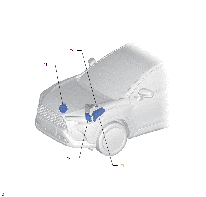
ILLUSTRATION
|
*1
|
GENERATOR ASSEMBLY
|
*2
|
ECM
|
|
*3
|
BATTERY STATE SENSOR ASSEMBLY
|
*4
|
NO. 1 ENGINE ROOM RELAY BLOCK
|
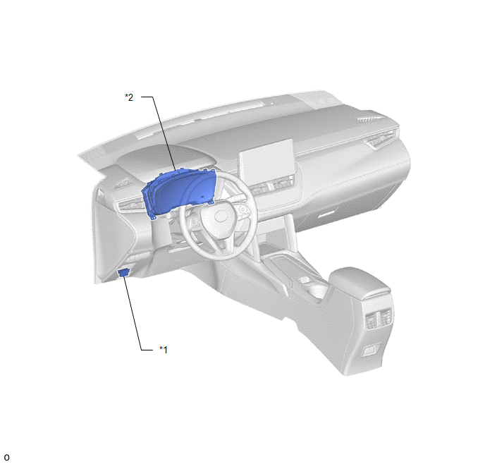
ILLUSTRATION
|
*1
|
COMBINATION METER ASSEMBLY
|
*2
|
DLC3
|
READ NEXT:
CAUTION / NOTICE / HINT
HINT:
*: Use the GTS.
PROCEDURE
1.
VEHICLE BROUGHT TO WORKSHOP
NEXT
PROBLEM SYMPTOMS TABLE
HINT:
Use the table below to help determine the cause of problem symptoms. If
multiple suspected areas are listed, the potential causes of the symptoms are
listed in
SEE MORE:
DESCRIPTION The air conditioning control assembly communicates with the air conditioning amplifier assembly via LIN communication.
If a malfunction occurs in the LIN communication system, the air conditioning amplifier assembly will not operate, even if the air conditioning control assembly is ope
DESCRIPTION Refer to DTC P034011. Click here
DTC No. Detection Item
DTC Detection Condition Trouble Area
MIL Note
P034015 Camshaft Position Sensor "A" Bank 1 or Single Sensor Circuit Short to Battery or Open
Diagnosis condition:
2 seconds or more ha


