Toyota Corolla Cross: Parts Location
PARTS LOCATION
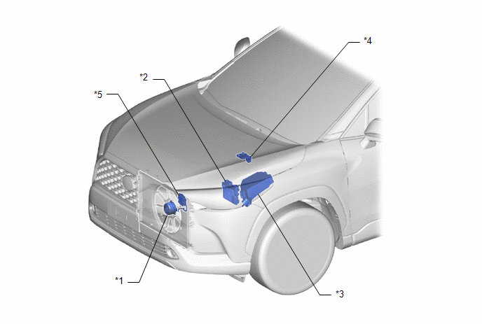
ILLUSTRATION
|
*1 | FAN WITH MOTOR ASSEMBLY |
*2 | ECM |
|
*3 | NO. 1 ENGINE ROOM RELAY BLOCK AND NO. 1 JUNCTION BLOCK ASSEMBLY
- EFI-MAIN NO. 1 FUSE - FAN NO. 2 FUSE - EFI NO. 3 FUSE
- EFI-MAIN NO. 1 Relay |
*4 | FUSIBLE LINK BLOCK ASSEMBLY
- ALT FUSE |
|
*5 | COOLING FAN ECU | | |
READ NEXT:
PROBLEM SYMPTOMS TABLE
HINT:
Use the table below to help determine the cause of problem symptoms. If multiple suspected areas are listed, the potential causes of the symptoms are listed in order
ON-VEHICLE INSPECTION PROCEDURE
1. INSPECT COOLING FAN SYSTEM CAUTION: To prevent injury due to contact with an operating cooling fan, keep your hands and clothing away from the cooling fan when ins
SEE MORE:
DESCRIPTION
Refer to DTC C050C12
Click here
DTC No.
Detection Item
DTC Detection Condition
Trouble Area
C050C1C
Left Rear Wheel Speed Sensor Circuit Voltage Out of
Range
When the vehicle is being driven
REMOVAL CAUTION / NOTICE / HINT COMPONENTS (REMOVAL)
Procedure Part Name Code
1 AIR CONDITIONER UNIT ASSEMBLY
- -
- -
2 TRANSPONDER KEY ECU ASSEMBLY
89780 -
- - CAUTION / NOTICE / HINT
The necessary procedures (adj


