Toyota Corolla Cross Owners & Service Manuals

Toyota Corolla Cross: Parts Location

PARTS LOCATION

ILLUSTRATION
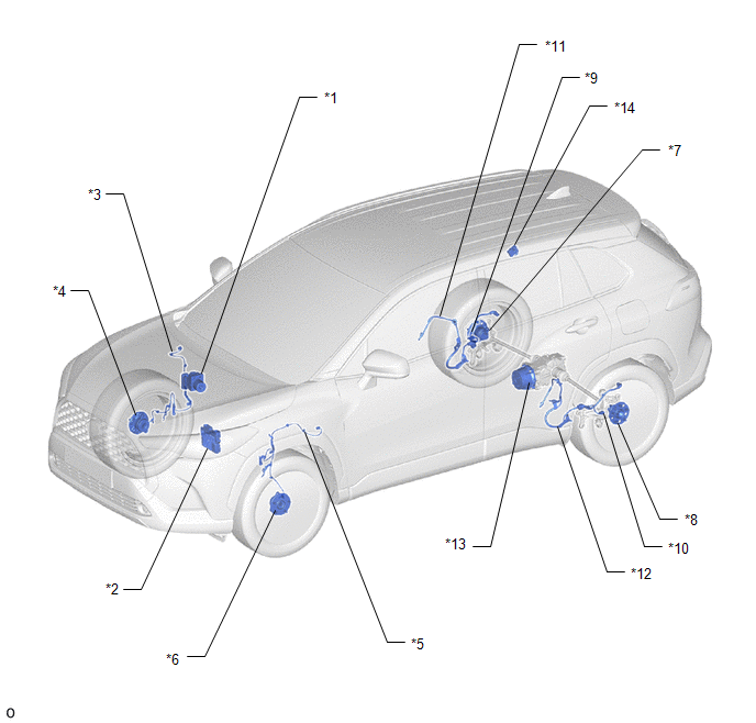
*1

BRAKE ACTUATOR ASSEMBLY

- SKID CONTROL ECU

*2

ECM

*3

FRONT SPEED SENSOR RH

*4

FRONT AXLE HUB SUB-ASSEMBLY RH

- FRONT SPEED SENSOR ROTOR RH

*5

FRONT SPEED SENSOR LH

*6

FRONT AXLE HUB SUB-ASSEMBLY LH

- FRONT SPEED SENSOR ROTOR LH

*7

REAR AXLE HUB AND BEARING ASSEMBLY RH

- REAR SPEED SENSOR ROTOR RH

*8

REAR AXLE HUB AND BEARING ASSEMBLY LH

- REAR SPEED SENSOR ROTOR LH

*9

REAR SKID CONTROL SENSOR RH

*10

REAR SKID CONTROL SENSOR LH

*11

NO. 1 PARKING BRAKE WIRE ASSEMBLY

*12

NO. 2 PARKING BRAKE WIRE ASSEMBLY

*13

4WD LINEAR SOLENOID (TRANSMISSION COUPLING ASSEMBLY)

*14

4WD ECU ASSEMBLY

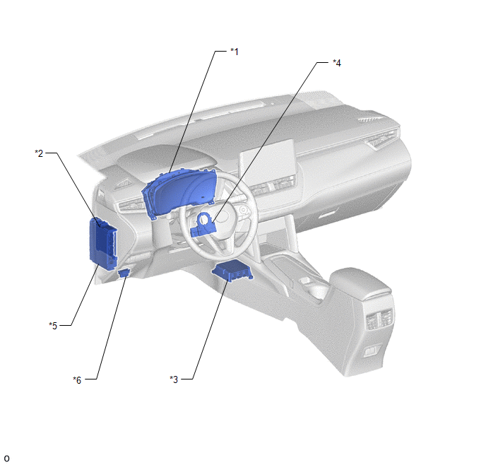
ILLUSTRATION

*1

COMBINATION METER ASSEMBLY

- AWD WARNING MESSAGE (MULTI-INFORMATION DISPLAY)

*2

MAIN BODY ECU (MULTIPLEX NETWORK BODY ECU)

*3

AIRBAG ECU ASSEMBLY

- YAW RATE AND ACCELERATION SENSOR

*4

STEERING SENSOR

*5

POWER DISTRIBUTION BOX ASSEMBLY

- ECU-IGR NO. 5 FUSE

- ECU-DCC NO.1 FUSE

*6

DLC3

    READ NEXT:

     System Diagram

    SYSTEM DIAGRAM

     How To Proceed With Troubleshooting

    CAUTION / NOTICE / HINT HINT: Use the following procedure listed to troubleshoot the Dynamic Torque Control AWD System. *: Use the GTS. PROCEDURE 1. VEHICLE BROU

     Calibration

    CALIBRATION NOTICE: Initial AWD functions such as acceleration are sometimes affected unless backup memory is cleared. When the yaw rate and acceleration sensor (airbag ECU assembly) is rep

    SEE MORE:

     Cylinder 1 Injector Circuit Range/Performance (P02EE00,P02EF00,P02F000,P02F100)

    DESCRIPTION By using Partial Lift Fuel Injection Control to spray fuel before the needle inside each direct fuel injector assembly has fully opened, the injection of fuel by the direct fuel injector assembly can be precisely controlled at partial lift. Due to the influence on the injected fuel volum

     IG Circuit Short to Ground (B227111)

    DESCRIPTION This DTC is stored when a malfunction in the IG drive circuit or IG hold circuit of the certification ECU (smart key ECU assembly) or a malfunction in the IG output circuit between the output terminal of the certification ECU (smart key ECU assembly) and IG relay is detected. DTC N

    © 2020-2026 Copyright www.tcorollacross.com PT NL