Toyota Corolla Cross: Parts Location
Toyota Corolla Cross (2022-2026) Service Manual / Audio & Visual & Telematics / Telematics / Telematics System / Parts Location
PARTS LOCATION
ILLUSTRATION
|
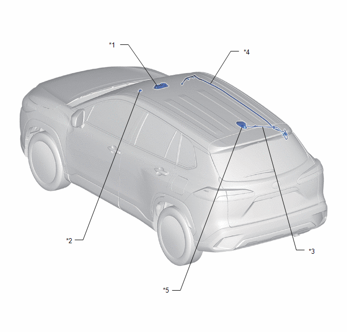
*1 |
MAP LIGHT ASSEMBLY - MANUAL (SOS) SWITCH |
*2 |
TELEPHONE MICROPHONE ASSEMBLY |
|
*3 |
ROOF ANTENNA ASSEMBLY |
*4 |
NO. 2 ANTENNA CORD SUB-ASSEMBLY |
|
*5 |
NO. 3 ANTENNA CORD SUB-ASSEMBLY |
- |
- |
ILLUSTRATION
|
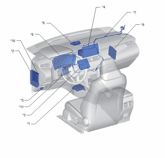
*1 |
AIRBAG ECU ASSEMBLY |
*2 |
POWER DISTRIBUTION BOX ASSEMBLY - ECU-IGR NO. 2 FUSE - DCM FUSE |
|
*3 |
DCM(TELEMATICS TRANSCEIVER) - MOBILEPHONE BATTERY |
*4 |
RADIO AND DISPLAY RECEIVER ASSEMBLY |
|
*5 |
DLC3 |
*6 |
NAVIGATION ANTENNA ASSEMBLY |
|
*7 |
ANTENNA CORD SUB-ASSEMBLY |
*8 |
COMBINATION METER ASSEMBLY |
|
*9 |
CERTIFICATION ECU (SMART KEY ECU ASSEMBLY) |
*10 |
MAIN BODY ECU (MULTIPLEX NETWOR BODY ECU) |
|
*11 |
AIR CONDITIONING AMPLIFIER ASSEMBLY |
- |
- |


