Toyota Corolla Cross: System Diagram
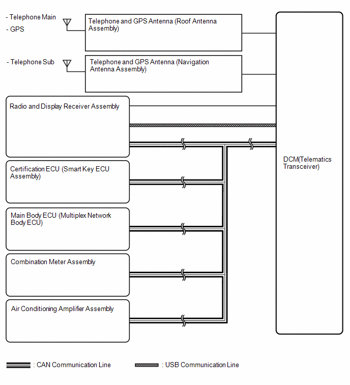
SYSTEM DIAGRAM
READ NEXT:
SYSTEM DESCRIPTION
OUTLINE
(a) Remote Connect, which enables the user to check the vehicle
status and operate the vehicle from a remote location, has been used.
(b) Remote Connect is available by
CAUTION / NOTICE / HINT
HINT:
Use the following procedure to troubleshoot the telematics system.
*: Use the GTS.
PROCEDURE
1.
VEHICLE BROUGHT TO WORKSHOP
OPERATION CHECK
HINT:
This function shows the telematics network status when the DCM (telematics
transceiver) was operated. Use this when no DTC is present but this telematics
system was
SEE MORE:
REMOVAL CAUTION / NOTICE / HINT COMPONENTS (REMOVAL)
Procedure Part Name Code
1 FRONT FENDER MOULDING SUB-ASSEMBLY LH
75602A
- -
2 FRONT FENDER MOULDING SUB-ASSEMBLY RH
75601A
- -
3 FRONT BUMPER ASSEMBLY
DESCRIPTION
Refer to DTC C050012
Click here
DTC No.
Detection Item
DTC Detection Condition
Trouble Area
C05001C
Left Front Wheel Speed Sensor Circuit Voltage Out of
Range
When the vehicle is being driven
 System Description
 Removal
