Toyota Corolla Cross: Parts Location
PARTS LOCATION
ILLUSTRATION
|
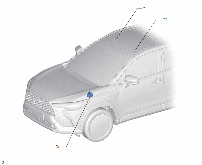
*1 |
TELEPHONE MICROPHONE ASSEMBLY (RH) |
*2 |
TELEPHONE MICROPHONE ASSEMBLY (LH) |
|
*3 |
SKID CONTROL ECU (BRAKE ACTUATOR ASSEMBLY) |
- |
- |
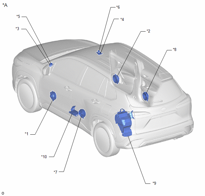
ILLUSTRATION
|
*A |
w/ Telematics Transceiver |
- |
- |
|
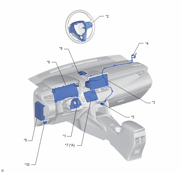
*1 |
SPIRAL CABLE SUB-ASSEMBLY |
*2 |
STEERING PAD SWITCH ASSEMBLY |
|
*3 |
RADIO AND DISPLAY RECEIVER ASSEMBLY |
*4 |
ANTENNA CORD SUB-ASSEMBLY |
|
*5 |
STEREO JACK ADAPTER ASSEMBLY |
*6 |
COMBINATION METER ASSEMBLY |
|
*7 |
TELEMATICS TRANSCEIVER |
*8 |
NAVIGATION ANTENNA ASSEMBLY |
|
*9 |
POWER DISTRIBUTION BOX ASSEMBLY |
*10 |
DLC3 |
ILLUSTRATION
|
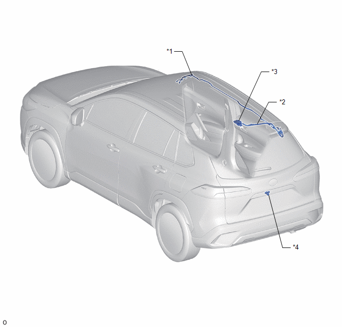
*1 |
NO. 2 ANTENNA CORD SUB-ASSEMBLY |
*2 |
NO. 3 ANTENNA CORD SUB-ASSEMBLY |
|
*3 |
ROOF ANTENNA ASSEMBLY |
*4 |
REAR TELEVISION CAMERA ASSEMBLY |
ILLUSTRATION
|
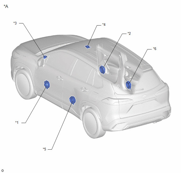
*A |
for 6 Speakers |
- |
- |
|
*1 |
FRONT NO. 1 SPEAKER ASSEMBLY (LH) |
*2 |
FRONT NO. 1 SPEAKER ASSEMBLY (RH) |
|
*3 |
FRONT NO. 2 SPEAKER ASSEMBLY (LH) |
*4 |
FRONT NO. 2 SPEAKER ASSEMBLY (RH) |
|
*5 |
REAR SPEAKER ASSEMBLY (LH) |
*6 |
REAR SPEAKER ASSEMBLY (RH) |
ILLUSTRATION
|
*A |
for 9 Speakers |
- |
- |
|
*1 |
FRONT NO. 1 SPEAKER ASSEMBLY (LH) |
*2 |
FRONT NO. 1 SPEAKER ASSEMBLY (RH) |
|
*3 |
FRONT NO. 2 SPEAKER ASSEMBLY (LH) |
*4 |
FRONT NO. 2 SPEAKER ASSEMBLY (RH) |
|
*5 |
FRONT NO. 3 SPEAKER ASSEMBLY (LH) |
*6 |
FRONT NO. 3 SPEAKER ASSEMBLY (RH) |
|
*7 |
REAR SPEAKER ASSEMBLY (LH) |
*8 |
REAR SPEAKER ASSEMBLY (RH) |
|
*9 |
NO. 1 SPEAKER WITH BOX ASSEMBLY |
*10 |
STEREO COMPONENT AMPLIFIER ASSEMBLY |


