Toyota Corolla Cross: On-vehicle Inspection
ON-VEHICLE INSPECTION
CAUTION / NOTICE / HINT
HINT:
- Use the same procedure for the RH side and LH side.
- The following procedure is for the LH side.
PROCEDURE
1. REMOVE FRONT WHEEL
Click here .gif)
2. SEPARATE FRONT DISC BRAKE CALIPER ASSEMBLY
Click here
3. REMOVE FRONT DISC
Click here
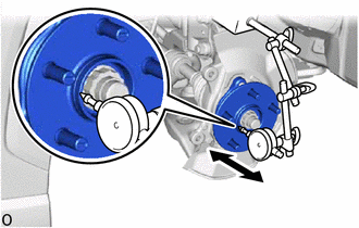
4. INSPECT FRONT AXLE HUB BEARING LOOSENESS
|
(a) Using a dial indicator with magnetic base, check for looseness near
the center of the front axle hub sub-assembly.
Maximum Looseness:
0.05 mm (0.00197 in.)
NOTICE:
- Ensure that the dial indicator is set perpendicular to the measurement
surface.
- Keep the magnet of the dial indicator away from the front axle hub
sub-assembly and front speed sensor.
|
|
(b) If the looseness exceeds the maximum, replace the front axle hub sub-assembly.
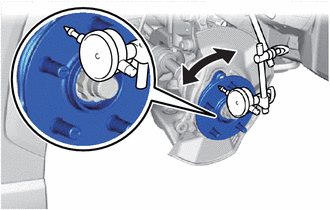
5. INSPECT FRONT AXLE HUB RUNOUT
|
(a) Using a dial indicator with magnetic base, check for runout on the
surface of the front axle hub sub-assembly outside the front axle hub bolts.
Maximum Runout:
0.05 mm (0.00197 in.)
NOTICE:
- Ensure that the dial indicator is set perpendicular to the measurement
surface.
- Make sure to set the tip of the dial indicator towards the outside
of the front axle hub bolts.
- Keep the magnet of the dial indicator away from the front axle hub
sub-assembly and front speed sensor.
|
|
(b) If the runout exceeds the maximum, replace the front axle hub sub-assembly.
6. INSTALL FRONT DISC
Click here
7. INSTALL FRONT DISC BRAKE CALIPER ASSEMBLY
Click here
8. INSTALL FRONT WHEEL
Click here
READ NEXT:
REMOVAL
CAUTION / NOTICE / HINT
COMPONENTS (REMOVAL)
Procedure
Part Name Code
1
FRONT WHEEL
-
-
INSTALLATION
CAUTION / NOTICE / HINT
COMPONENTS (INSTALLATION)
Procedure
Part Name Code
1
FRONT AXLE HUB SUB-ASSEMBLY
Components
COMPONENTS
ILLUSTRATION
*1
FRONT AXLE HUB BOLT
*2
FRONT DISC
*3
FRONT DISC BRAKE CALIPER ASSEMBLY
-
SEE MORE:
DIAGNOSTIC TROUBLE CODE CHART Smart Key System (for Entry Function)
DTC No. Detection Item
Link B27A113
Driver Side Electrical Antenna Circuit Open
B27A213 Front Passenger Side Electrical Antenna Circuit Open
B27A813 Outside Luggage Compar
The PKSB (Parking Support
Brake) consists of the following
functions that operate
when driving at a low
speed or backing up, such
as when parking. When the
system determines that the
possibility of a collision
with a detected object is
high, a warning operates to
urge the driver to take evasive
acti