Toyota Corolla Cross: M20a-fxs Spark Plug
Removal
REMOVAL
CAUTION / NOTICE / HINT
COMPONENTS (REMOVAL)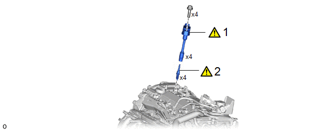
|
Procedure |
Part Name Code |
.png) |
.png) |
.png) |
|
|---|---|---|---|---|---|
|
1 |
IGNITION COIL ASSEMBLY |
19500 |
|
- |
- |
|
2 |
SPARK PLUG |
19100P |
|
- |
- |
CAUTION / NOTICE / HINT
NOTICE:
This procedure includes the removal of small-head bolts. Refer to Small-Head Bolts of Basic Repair Hint to identify the small-head bolts.
Click here .gif)
PROCEDURE
1. REMOVE IGNITION COIL ASSEMBLY
|
|
Click here |
2. REMOVE SPARK PLUG
|
|
NOTICE: If a spark plug has been struck or dropped, replace it. |
.png)
Installation
INSTALLATION
CAUTION / NOTICE / HINT
COMPONENTS (INSTALLATION)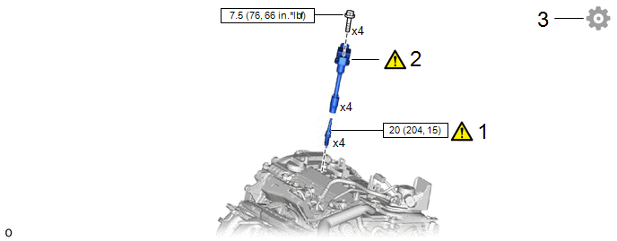
|
Procedure |
Part Name Code |
.png) |
.png) |
.png) |
|
|---|---|---|---|---|---|
|
1 |
SPARK PLUG |
19100P |
|
- |
- |
|
2 |
IGNITION COIL ASSEMBLY |
19500 |
|
- |
- |
|
3 |
PERFORM INITIALIZATION |
- |
- |
- |
|
.png) |
N*m (kgf*cm, ft.*lbf): Specified torque |
- |
- |
CAUTION / NOTICE / HINT
NOTICE:
This procedure includes the installation of small-head bolts. Refer to Small-Head Bolts of Basic Repair Hint to identify the small-head bolts.
Click here .gif)
PROCEDURE
1. INSTALL SPARK PLUG
|
|
NOTICE: If a spark plug has been struck or dropped, replace it. HINT: Perform "Inspection After Repair" after replacing a spark plug. Click here |
(a) Install the 4 spark plugs to the cylinder head sub-assembly.
Torque:
20 N·m {204 kgf·cm, 15 ft·lbf}
2. INSTALL IGNITION COIL ASSEMBLY
|
|
Click here |
3. PERFORM INITIALIZATION
(a) Perform "Inspection After Repair" after replacing an ignition coil assembly or spark plug.
Click here


