Toyota Corolla Cross: Lost Communication with Cruise Control Front Distance Range Sensor Single Sensor or Center Missing Message (U023587)
DESCRIPTION
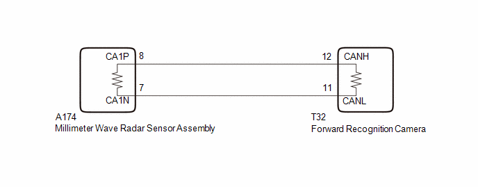
The forward recognition camera communicates with the millimeter wave radar sensor assembly via CAN communication line. If communication with the millimeter wave radar sensor assembly stops, the forward recognition camera stores DTC U023587.
|
DTC No. |
Detection Item |
DTC Detection Condition |
Trouble Area |
DTC Output from |
|---|---|---|---|---|
|
U023587 |
Lost Communication with Cruise Control Front Distance Range Sensor Single Sensor or Center Missing Message |
When a communication error between forward recognition camera and millimeter wave radar sensor assembly is detected |
|
Front Recognition Camera |
HINT:
If the DTCs are output simultaneously, the inspection area can be narrowed down.
|
Pattern |
DTC output part name (Display on GTS) |
Suspected Area (Malfunction Status) |
|
|---|---|---|---|
|
Forward Recognition Camera |
Millimeter Wave Radar Sensor Assembly |
||
|
Front Recognition Camera |
Front Radar Sensor |
||
|
U023587 |
U010487 |
||
| ○: DTC is output
-: DTC is not output |
|||
|
Pattern 1 |
○ |
○ |
Harness or connector (Open or short) |
|
Millimeter wave radar sensor assembly (Internal malfunction) |
|||
|
Forward recognition camera (Internal malfunction) |
|||
|
Pattern 2 |
○ |
- |
Millimeter wave radar sensor assembly (Internal malfunction) |
|
Forward recognition camera (Internal malfunction) |
|||
WIRING DIAGRAM
CAUTION / NOTICE / HINT
NOTICE:
- When replacing the millimeter wave radar sensor assembly, always replace it with a new one. If a millimeter wave radar sensor assembly which was installed to another vehicle is used, the information stored in the millimeter wave radar sensor assembly will not match the information from the vehicle and a DTC may be stored.
- When the millimeter wave radar sensor assembly has been replaced with
a new one, it is necessary to perform millimeter wave radar sensor assembly
beam axis alignment and to clear the vehicle control history. Before performing
the Driving Adjustment, make sure to read Before Starting Driving Adjustment.
HINT:
Beam axis alignment of the millimeter wave radar sensor assembly can be performed using either Triangle Target, Flat Surface Target or Driving Adjustment.
Triangle Target: Click here
.gif)
Flat Surface Target: Click here
Driving Adjustment: Click here
- When replacing the forward recognition camera, always replace it with a new one. If a forward recognition camera which was installed to another vehicle is used, the information stored in the forward recognition camera will not match the information from the vehicle and a DTC may be stored.
- When the forward recognition camera has been replaced with a new one,
make sure to clear all stored vehicle control history of each system and
the forward recognition camera beam axis alignment data.
HINT:
Forward recognition camera beam axis alignment can be performed by using "One Time Recognition", "Driving Adjustment" or "Camera Axis Adjustment Value Write".
One Time Recognition: Click here
Driving Adjustment: Click here
Camera Axis Adjustment Value Write: Click here
- If the forward recognition camera has been replaced with a new one,
make sure to perform Software Version Confirmation.
Click here
- After the ignition switch is turned off, there may be a waiting time
before disconnecting the negative (-) auxiliary battery terminal.
Click here
HINT:
When disconnecting and reconnecting the auxiliary battery, there is an automatic learning function that completes learning when the respective system is used.
Click here
PROCEDURE
|
1. |
CHECK FOR DTCs |
(a) Read each DTC and check the diagnosis pattern using the table below.
Chassis > Front Recognition Camera > Trouble Codes Body Electrical > Front Radar Sensor > Trouble Codes|
Pattern |
DTC output part name (Display on GTS) |
|
|---|---|---|
|
Front Recognition Camera |
Front Radar Sensor |
|
|
Pattern 1 |
U023587 |
U010487 |
|
Pattern 2 |
U023587 |
- |
|
Result |
Proceed to |
|---|---|
|
Pattern 1 |
A |
|
Pattern 2 |
B |
| B | .gif)
|
GO TO STEP 4 |
|
.gif)
|
2. |
CHECK CAN MAIN WIRE (FORWARD RECOGNITION CAMERA) |
(a) Disconnect the cable from the negative (-) auxiliary battery terminal.
(b) Disconnect the T32 forward recognition camera connector.
(c) Measure the resistance according to the value(s) in the table below.
Standard Resistance:
|
Tester Connection |
Condition |
Specified Condition |
|---|---|---|
|
T32-12 (CANH) - T32-11 (CANL) |
Cable disconnected from negative (-) auxiliary battery terminal |
108 to 132 Ω |
|
T32-12 (CANH) - Body ground |
Cable disconnected from negative (-) auxiliary battery terminal |
200 Ω or higher |
|
T32-11 (CANL) - Body ground |
Cable disconnected from negative (-) auxiliary battery terminal |
200 Ω or higher |
|
T32-12 (CANH) - +B |
Cable disconnected from negative (-) auxiliary battery terminal |
6 kΩ or higher |
|
T32-11 (CANL) - +B |
Cable disconnected from negative (-) auxiliary battery terminal |
6 kΩ or higher |
| OK |
|
REPLACE FORWARD RECOGNITION CAMERA |
|
|
3. |
CHECK CAN MAIN WIRE (MILLIMETER WAVE RADAR SENSOR ASSEMBLY) |
(a) Connect the T32 forward recognition camera connector.
(b) Disconnect the A174 millimeter wave radar sensor assembly connector.
(c) Measure the resistance according to the value(s) in the table below.
Standard Resistance:
|
Tester Connection |
Condition |
Specified Condition |
|---|---|---|
|
A174-8 (CA1P) - A174-7 (CA1N) |
Cable disconnected from negative (-) auxiliary battery terminal |
108 to 132 Ω |
|
A174-8 (CA1P) - Body ground |
Cable disconnected from negative (-) auxiliary battery terminal |
200 Ω or higher |
|
A174-7 (CA1N) - Body ground |
Cable disconnected from negative (-) auxiliary battery terminal |
200 Ω or higher |
|
A174-8 (CA1P) - +B |
Cable disconnected from negative (-) auxiliary battery terminal |
6 kΩ or higher |
|
A174-7 (CA1N) - +B |
Cable disconnected from negative (-) auxiliary battery terminal |
6 kΩ or higher |
| OK |
|
REPLACE MILLIMETER WAVE RADAR SENSOR ASSEMBLY NOTICE: Before replacing the millimeter wave radar sensor assembly, make sure to turn the ignition switch from off to ON and check for DTCs. |
| NG |
|
REPAIR OR REPLACE HARNESS OR CONNECTOR |
|
4. |
CHECK CONNECTION OF CONNECTORS |
(a) Check that the connectors are properly connected to the forward recognition camera and millimeter wave radar sensor assembly.
OK:
The connectors are properly connected
| NG |
|
REPAIR OR REPLACE CAN BUS HARNESS OR CONNECTOR |
|
|
5. |
CLEAR DTC |
(a) Clear the DTCs.
Chassis > Front Recognition Camera > Clear DTCs
|
|
6. |
CHECK FOR DTCs |
(a) Turn the ignition switch off.
(b) Turn the ignition switch to ON.
(c) Make sure that the DTC detection conditions are met.
HINT:
If the detection conditions are not met, the system cannot detect the malfunction.
(d) Check for DTCs.
Chassis > Front Recognition Camera > Trouble Codes|
Result |
Proceed to |
|---|---|
|
U023587 is not output |
A |
|
U023587 is output |
B |
| A |
|
END |
|
|
7. |
CHECK CAN WIRE (FORWARD RECOGNITION CAMERA) |
(a) Disconnect the cable from the negative (-) auxiliary battery terminal.
(b) Disconnect the T32 forward recognition camera connector.
(c) Measure the resistance according to the value(s) in the table below.
Standard Resistance:
|
Tester Connection |
Condition |
Specified Condition |
|---|---|---|
|
T32-12 (CANH) - T32-11 (CANL) |
Cable disconnected from negative (-) auxiliary battery terminal |
108 to 132 Ω |
| NG |
|
REPAIR OR REPLACE CAN BUS HARNESS OR CONNECTOR |
|
|
8. |
CHECK MILLIMETER WAVE RADAR SENSOR ASSEMBLY |
(a) Disconnect the T32 forward recognition camera connector.
(b) Using an oscilloscope, check the waveform.
OK:
|
Tester Connection |
Condition |
Tool Setting |
Specified Condition |
|---|---|---|---|
|
T32-12 (CANH) - T32-11 (CANL) |
Ignition switch ON |
1V/DIV., 100μs./DIV. |
Pulse generation |
| OK |
|
REPLACE FORWARD RECOGNITION CAMERA |
| NG |
|
REPLACE MILLIMETER WAVE RADAR SENSOR ASSEMBLY |
READ NEXT:
 Internal Control Module Software Incompatibility Not Programmed (U030051,U030057)
DESCRIPTION
for Gasoline Model:
Forward recognition camera receives Powertrain Information from ECM
via CAN communication line.
If the forward recognition camera cannot confirm the Pow
Software Incompatibility with Body Control Module Not Programmed (U032251)
DESCRIPTION
Forward recognition camera receives vehicle specification information
from the main body ECU (multiplex network body ECU) via CAN communication line.
If the forward recognition camera
Software Incompatibility with Body Control Module Invalid/Incompatible Software
Component (U032257)
DESCRIPTION
Forward recognition camera receives vehicle specification information
from the main body ECU (multiplex network body ECU) via CAN communication line.
When the vehicle specification in
SEE MORE:
 Installation
INSTALLATION CAUTION / NOTICE / HINT COMPONENTS (INSTALLATION)
Procedure Part Name Code
1 CLEAN QUARTER WINDOW ASSEMBLY
62720A
- -
2 QUARTER WINDOW ASSEMBLY
62720A
- -
3 INSPECT FOR LEAK
-
-
Torque Converter Clutch Pressure Control Solenoid Control Circuit Short to Ground
or Open (P275614)
DESCRIPTION
Refer to DTC P275612.
Click here
DTC No.
Detection Item
DTC Detection Condition
Trouble Area
MIL
Memory
Note
P275614
Torque Converter Clutch Pressure Control Solenoid Control Cir
