Toyota Corolla Cross: Linear Solenoid Power Supply System Malfunction (C120C)
DESCRIPTION
When a malfunction has occurred in the linear solenoid power source circuit, the 4WD ECU assembly stores DTC C120C.
|
DTC No. |
Detection Item |
DTC Detection Condition |
Trouble Area |
|---|---|---|---|
|
C120C |
Linear Solenoid Power Supply System Malfunction |
|
|
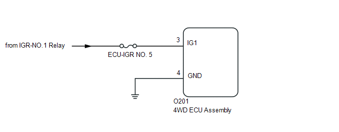
WIRING DIAGRAM
CAUTION / NOTICE / HINT
NOTICE:
Inspect the fuses for circuits related to this system before performing the following inspection procedure.
PROCEDURE
|
1. |
CHECK HARNESS AND CONNECTOR (IG1 TERMINAL) |
|
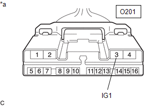
(a) Disconnect the 4WD ECU assembly connector. |
|
(b) Turn the ignition switch to ON.
(c) Measure the voltage according to the value(s) in the table below.
Standard Voltage:
|
Tester Connection |
Switch Condition |
Specified Condition |
|---|---|---|
|
O201-3 (IG1) -Body ground |
Ignition switch ON |
11 to 14 V |
| NG | .gif) |
REPAIR OR REPLACE HARNESS OR CONNECTOR |
|
.gif)
|
2. |
CHECK HARNESS AND CONNECTOR (GND TERMINAL) |
(a) Turn the ignition switch off.
(b) Measure the resistance according to the value(s) in the table below.
Standard Resistance:
|
Tester Connection |
Condition |
Specified Condition |
|---|---|---|
|
O201-4 (GND) -Body ground |
Always |
Below 1 Ω |
| NG | |
REPAIR OR REPLACE HARNESS OR CONNECTOR |
|
|
3. |
RECONFIRM DTC |
(a) Clear the DTC.
Chassis > Four Wheel Drive > Clear DTCs(b) Turn the ignition switch to ON.
(c) Check that no DTCs other than DTC C120C have been output.
Chassis > Four Wheel Drive > Trouble Codes|
Result |
Proceed to |
|---|---|
|
DTCs other than C120C are not output |
A |
|
DTCs other than C120C are output |
B |
| A | |
REPLACE 4WD ECU ASSEMBLY |
.gif)
| B | |
REPAIR CIRCUIT INDICATED BY OUTPUT CODE |


