Toyota Corolla Cross: Left Rear Wheel Speed Sensor Internal Electronic Failure (C050C49)
DESCRIPTION
When the system is starting up and the skid control ECU (brake actuator assembly) detects a speed sensor circuit malfunction via the speed sensor circuit self-diagnosis function, this DTC is stored.
|
DTC No. |
Detection Item |
DTC Detection Condition |
Trouble Area |
|---|---|---|---|
|
C050C49 |
Left Rear Wheel Speed Sensor Internal Electronic Failure |
A circuit malfunction in the speed sensor is detected during the self test. |
|
- *1: for AWD
- *2: for 2WD
WIRING DIAGRAM
Refer to DTC C050C12.
Click here .gif)
PROCEDURE
|
1. |
CHECK VEHICLE |
(a) Check the vehicle specification.
|
Result |
Proceed to |
|---|---|
|
for 2WD |
A |
|
for AWD |
B |
| B | .gif)
|
GO TO STEP 13 |
|
.gif)
|
2. |
CHECK HARNESS AND CONNECTOR (SENSOR CIRCUIT) |
|
(a) Make sure that there is no looseness at the locking part and the connecting part of the connectors. OK: The connector is securely connected. |
|
.png)
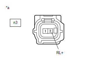
(b) Disconnect the n3 rear speed sensor LH (rear axle hub and bearing assembly LH) connector.
(c) Check both the connector case and the terminals for deformation and corrosion.
OK:
No deformation or corrosion.
(d) Turn the ignition switch to ON.
(e) Measure the voltage according to the value(s) in the table below.
Standard Voltage:
|
Tester Connection |
Condition |
Specified Condition |
|---|---|---|
|
n3-2 (RL+) - n3-1 (RL-) |
Ignition switch ON |
11 to 14 V |
| NG |
|
GO TO STEP 8 |
|
|
3. |
CHECK HARNESS AND CONNECTOR (SENSOR POWER SOURCE CIRCUIT) |
|
(a) Make sure that there is no looseness at the locking part and the connecting part of the connectors. OK: The connector is securely connected. |
|
(b) Disconnect the n3 rear speed sensor LH (rear axle hub and bearing assembly LH) connector.
(c) Check both the connector case and the terminals for deformation and corrosion.
OK:
No deformation or corrosion.
(d) Measure the voltage according to the value(s) in the table below.
Standard Voltage:
|
Tester Connection |
Condition |
Specified Condition |
|---|---|---|
|
n3-2 (RL+) - Body ground |
Ignition switch off |
Below 1.5 V |
| NG |
|
GO TO STEP 6 |
|
|
4. |
INSPECT NO. 2 PARKING BRAKE WIRE ASSEMBLY |
|
(a) Make sure that there is no looseness at the locking part and the connecting part of the connectors. OK: The connector is securely connected. |
|
.png)
(b) Disconnect the n3 skid control sensor wire LH (No. 2 parking brake wire assembly) connector.
(c) Disconnect the nO2 skid control sensor wire LH (No. 2 parking brake wire assembly) connector.
(d) Check both the connector case and the terminals for deformation and corrosion.
OK:
No deformation or corrosion.
(e) Measure the resistance according to the value(s) in the table below.
Standard Resistance:
|
Tester Connection |
Condition |
Specified Condition |
|---|---|---|
|
n3-1 (RL-) or nO2-1 (RL-) - Body ground and other terminals |
Always |
10 kΩ or higher |
| NG |
|
REPLACE NO. 2 PARKING BRAKE WIRE ASSEMBLY |
|
|
5. |
CHECK HARNESS AND CONNECTOR (NO. 2 PARKING BRAKE WIRE ASSEMBLY - BRAKE ACTUATOR ASSEMBLY) |
(a) Make sure that there is no looseness at the locking part and the connecting part of the connectors.
OK:
The connector is securely connected.
(b) Disconnect the A151 skid control ECU (brake actuator assembly) connector.
(c) Disconnect the nO2 skid control sensor wire LH (No. 2 parking brake wire assembly) connector.
(d) Check both the connector case and the terminals for deformation and corrosion.
OK:
No deformation or corrosion.
(e) Measure the resistance according to the value(s) in the table below.
Standard Resistance:
|
Tester Connection |
Condition |
Specified Condition |
|---|---|---|
|
nO2-1 (RL-) or A151-23 (RL-) - Body ground |
Always |
10 kΩ or higher |
| OK |
|
REPLACE REAR AXLE HUB AND BEARING ASSEMBLY LH |
| NG |
|
REPAIR OR REPLACE HARNESS OR CONNECTOR |
|
6. |
CHECK HARNESS AND CONNECTOR (SENSOR POWER SOURCE CIRCUIT) |
|
(a) Make sure that there is no looseness at the locking part and the connecting part of the connectors. OK: The connector is securely connected. |
|
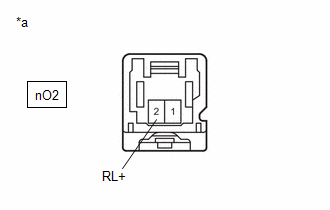
(b) Disconnect the nO2 skid control sensor wire LH (No. 2 parking brake wire assembly) connector.
(c) Check both the connector case and the terminals for deformation and corrosion.
OK:
No deformation or corrosion.
(d) Measure the voltage according to the value(s) in the table below.
Standard Voltage:
|
Tester Connection |
Condition |
Specified Condition |
|---|---|---|
|
nO2-2 (RL+) - Body ground |
Ignition switch off |
Below 1.5 V |
| OK |
|
REPLACE NO. 2 PARKING BRAKE WIRE ASSEMBLY |
|
|
7. |
CHECK HARNESS AND CONNECTOR (NO. 2 PARKING BRAKE WIRE ASSEMBLY - BRAKE ACTUATOR ASSEMBLY) |
|
(a) Make sure that there is no looseness at the locking part and the connecting part of the connectors. OK: The connector is securely connected. |
|
(b) Disconnect the A151 skid control ECU (brake actuator assembly) connector.
(c) Disconnect the nO2 skid control sensor wire LH (No. 2 parking brake wire assembly) connector.
(d) Check both the connector case and the terminals for deformation and corrosion.
OK:
No deformation or corrosion.
(e) Measure the voltage according to the value(s) in the table below.
Standard Voltage:
|
Tester Connection |
Condition |
Specified Condition |
|---|---|---|
|
nO2-2 (RL+) - Body ground |
Always |
Below 1.5 V |
| OK |
|
REPLACE BRAKE ACTUATOR ASSEMBLY |
| NG |
|
REPAIR OR REPLACE HARNESS OR CONNECTOR |
|
8. |
CHECK HARNESS AND CONNECTOR (SENSOR CIRCUIT) |
|
(a) Make sure that there is no looseness at the locking part and the connecting part of the connectors. OK: The connector is securely connected. |
|
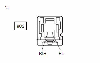
(b) Disconnect the nO2 skid control sensor wire LH (No. 2 parking brake wire assembly) connector.
(c) Check both the connector case and the terminals for deformation and corrosion.
OK:
No deformation or corrosion.
(d) Turn the ignition switch to ON.
(e) Measure the voltage according to the value(s) in the table below.
Standard Voltage:
|
Tester Connection |
Condition |
Specified Condition |
|---|---|---|
|
nO2-2 (RL+) - nO2-1 (RL-) |
Ignition switch ON |
11 to 14 V |
| OK |
|
REPLACE NO. 2 PARKING BRAKE WIRE ASSEMBLY |
|
|
9. |
CHECK HARNESS AND CONNECTOR (SENSOR POWER SOURCE CIRCUIT) |
|
(a) Make sure that there is no looseness at the locking part and the connecting part of the connectors. OK: The connector is securely connected. |
|
(b) Disconnect the nO2 skid control sensor wire LH (No. 2 parking brake wire assembly) connector.
(c) Check both the connector case and the terminals for deformation and corrosion.
OK:
No deformation or corrosion.
(d) Turn the ignition switch to ON.
(e) Measure the voltage according to the value(s) in the table below.
Standard Voltage:
|
Tester Connection |
Condition |
Specified Condition |
|---|---|---|
|
nO2-2 (RL+) - Body ground |
Ignition switch ON |
11 to 14 V |
| NG |
|
GO TO STEP 12 |
|
|
10. |
CHECK HARNESS AND CONNECTOR (NO. 2 PARKING BRAKE WIRE ASSEMBLY - BRAKE ACTUATOR ASSEMBLY) |
|
(a) Make sure that there is no looseness at the locking part and the connecting part of the connectors. OK: The connector is securely connected. |
|
.png)
(b) Disconnect the A151 skid control ECU (brake actuator assembly) connector.
(c) Disconnect the nO2 skid control sensor wire LH (No. 2 parking brake wire assembly) connector.
(d) Check both the connector case and the terminals for deformation and corrosion.
OK:
No deformation or corrosion.
(e) Measure the voltage according to the value(s) in the table below.
Standard Voltage:
|
Tester Connection |
Condition |
Specified Condition |
|---|---|---|
|
nO2-1 (RL-) - Body ground |
Always |
Below 1.5 V |
| NG |
|
REPAIR OR REPLACE HARNESS OR CONNECTOR |
|
|
11. |
CHECK HARNESS AND CONNECTOR (NO. 2 PARKING BRAKE WIRE ASSEMBLY - BRAKE ACTUATOR ASSEMBLY) |
(a) Make sure that there is no looseness at the locking part and the connecting part of the connectors.
OK:
The connector is securely connected.
(b) Disconnect the A151 skid control ECU (brake actuator assembly) connector.
(c) Disconnect the nO2 skid control sensor wire LH (No. 2 parking brake wire assembly) connector.
(d) Check both the connector case and the terminals for deformation and corrosion.
OK:
No deformation or corrosion.
(e) Measure the resistance according to the value(s) in the table below.
Standard Resistance:
|
Tester Connection |
Condition |
Specified Condition |
|---|---|---|
|
nO2-1 (RL-) - A151-23 (RL-) |
Always |
Below 1 Ω |
|
nO2-2 (RL+) or A151-39 (RL+) - nO2-1 (RL-) or A151-23 (RL-) |
Always |
10 kΩ or higher |
| OK |
|
REPLACE BRAKE ACTUATOR ASSEMBLY |
| NG |
|
REPAIR OR REPLACE HARNESS OR CONNECTOR |
|
12. |
CHECK HARNESS AND CONNECTOR (NO. 2 PARKING BRAKE WIRE ASSEMBLY - BRAKE ACTUATOR ASSEMBLY) |
(a) Make sure that there is no looseness at the locking part and the connecting part of the connectors.
OK:
The connector is securely connected.
(b) Disconnect the A151 skid control ECU (brake actuator assembly) connector.
(c) Disconnect the nO2 skid control sensor wire LH (No. 2 parking brake wire assembly) connector.
(d) Check both the connector case and the terminals for deformation and corrosion.
OK:
No deformation or corrosion.
(e) Measure the resistance according to the value(s) in the table below.
Standard Resistance:
|
Tester Connection |
Condition |
Specified Condition |
|---|---|---|
|
nO2-2 (RL+) - A151-39 (RL+) |
Always |
Below 1 Ω |
|
nO2-2 (RL+) or A151-39 (RL+) - Body ground |
Always |
10 kΩ or higher |
| OK |
|
REPLACE BRAKE ACTUATOR ASSEMBLY |
| NG |
|
REPAIR OR REPLACE HARNESS OR CONNECTOR |
|
13. |
CHECK HARNESS AND CONNECTOR (SENSOR CIRCUIT) |
|
(a) Make sure that there is no looseness at the locking part and the connecting part of the connectors. OK: The connector is securely connected. |
|
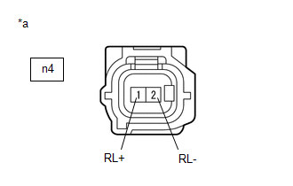
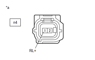
(b) Disconnect the n4 rear speed sensor LH connector.
(c) Check both the connector case and the terminals for deformation and corrosion.
OK:
No deformation or corrosion.
(d) Turn the ignition switch to ON.
(e) Measure the voltage according to the value(s) in the table below.
Standard Voltage:
|
Tester Connection |
Condition |
Specified Condition |
|---|---|---|
|
n4-1 (RL+) - n4-2 (RL-) |
Ignition switch ON |
11 to 14 V |
| NG |
|
GO TO STEP 8 |
|
|
14. |
CHECK HARNESS AND CONNECTOR (SENSOR POWER SOURCE CIRCUIT) |
|
(a) Make sure that there is no looseness at the locking part and the connecting part of the connectors. OK: The connector is securely connected. |
|
(b) Disconnect the n4 rear speed sensor LH connector.
(c) Check both the connector case and the terminals for deformation and corrosion.
OK:
No deformation or corrosion.
(d) Turn the ignition switch to ON.
(e) Measure the voltage according to the value(s) in the table below.
Standard Voltage:
|
Tester Connection |
Condition |
Specified Condition |
|---|---|---|
|
n4-1 (RL+) - Body ground |
Ignition switch off |
Below 1.5 V |
| NG |
|
GO TO STEP 6 |
|
|
15. |
INSPECT NO. 2 PARKING BRAKE WIRE ASSEMBLY |
|
(a) Make sure that there is no looseness at the locking part and the connecting part of the connectors. OK: The connector is securely connected. |
|
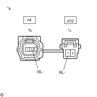
(b) Disconnect the n4 skid control sensor wire LH (No. 2 parking brake wire assembly) connector.
(c) Disconnect the nO2 skid control sensor wire LH (No. 2 parking brake wire assembly) connector.
(d) Check both the connector case and the terminals for deformation and corrosion.
OK:
No deformation or corrosion.
(e) Measure the resistance according to the value(s) in the table below.
Standard Resistance:
|
Tester Connection |
Condition |
Specified Condition |
|---|---|---|
|
n4-2 (RL-) or nO2-1 (RL-) - Body ground and other terminals |
Always |
10 kΩ or higher |
| NG |
|
REPLACE NO. 2 PARKING BRAKE WIRE ASSEMBLY |
|
|
16. |
CHECK HARNESS AND CONNECTOR (NO. 2 PARKING BRAKE WIRE ASSEMBLY - BRAKE ACTUATOR ASSEMBLY) |
(a) Make sure that there is no looseness at the locking part and the connecting part of the connectors.
OK:
The connector is securely connected.
(b) Disconnect the A151 skid control ECU (brake actuator assembly) connector.
(c) Disconnect the nO2 skid control sensor wire LH (No. 2 parking brake wire assembly) connector.
(d) Check both the connector case and the terminals for deformation and corrosion.
OK:
No deformation or corrosion.
(e) Measure the resistance according to the value(s) in the table below.
Standard Resistance:
|
Tester Connection |
Condition |
Specified Condition |
|---|---|---|
|
nO2-1 (RL-) or A151-23 (RL-) - Body ground |
Always |
10 kΩ or higher |
| OK |
|
REPLACE REAR SPEED SENSOR LH |
| NG |
|
REPAIR OR REPLACE HARNESS OR CONNECTOR |


