Toyota Corolla Cross: Installation
INSTALLATION
PROCEDURE
1. INSTALL PIPING CLAMP (for Suction Hose Sub-assembly)
(a) for Gasoline Model:
(1) Remove the vinyl tape from the suction pipe sub-assembly and suction hose sub-assembly.
| (2) Install a new piping clamp to the suction hose sub-assembly. NOTICE:
|
|
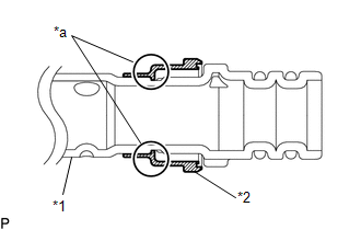
(3) Sufficiently apply compressor oil to 2 new O-rings and the fitting surfaces of the suction hose sub-assembly.
Compressor Oil:
ND-OIL 12 or equivalent
(4) Install the 2 O-rings to the suction hose sub-assembly.
NOTICE:
Keep the O-rings and O-ring fitting surfaces free from dirt and foreign matter.
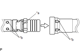
| (5) Align the alignment marks and connect the suction pipe sub-assembly and suction hose sub-assembly. NOTICE: Connect the parts by holding the tubes, not the piping clamp. |
|
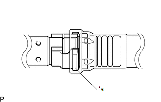
| (6) Securely insert the piping clamp to the point where the large diameter section of the piping clamp is covered by the suction pipe sub-assembly. NOTICE:
|
|
(b) for HEV Model:
(1) Remove the vinyl tape from the No. 2 air conditioning tube and accessory assembly and suction hose sub-assembly.
| (2) Install a new piping clamp to the suction hose sub-assembly. NOTICE:
|
|
(3) Sufficiently apply compressor oil to 2 new O-rings and the fitting surfaces of the suction hose sub-assembly.
Compressor Oil:
ND-OIL 11 or equivalent
(4) Install the 2 O-rings to the suction hose sub-assembly.
NOTICE:
Keep the O-rings and O-ring fitting surfaces free from dirt and foreign matter.
| (5) Align the alignment marks and connect the No. 2 air conditioning tube and accessory assembly and suction hose sub-assembly. NOTICE: Connect the parts by holding the tubes, not the piping clamp. |
|
| (6) Securely insert the piping clamp to the point where the large diameter section of the piping clamp is covered by the No. 2 air conditioning tube and accessory assembly. NOTICE:
|
|
2. INSTALL PIPING CLAMP (for Air Conditioning Tube and Accessory Assembly)
Click here .gif)
3. CHARGE AIR CONDITIONING SYSTEM WITH REFRIGERANT
Click here
4. WARM UP ENGINE (for Gasoline Model)
Click here
5. WARM UP COMPRESSOR (for HEV Model)
Click here
6. INSPECT FOR REFRIGERANT LEAK
Click here


