Toyota Corolla Cross: Installation
INSTALLATION
CAUTION / NOTICE / HINT
COMPONENTS (INSTALLATION)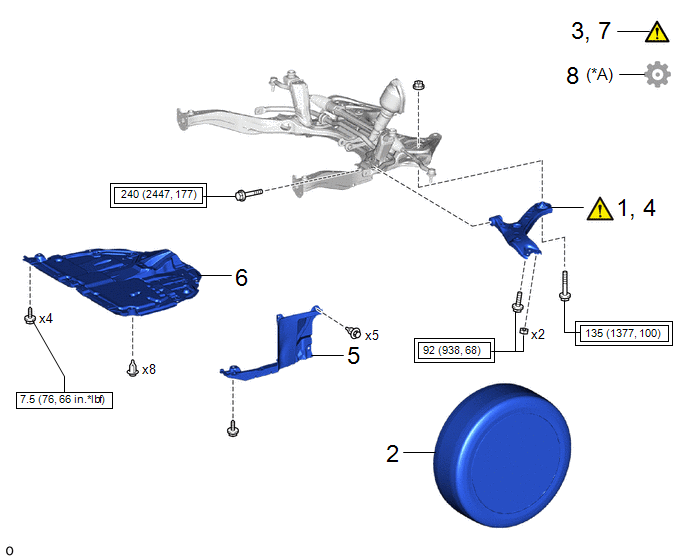
|
Procedure |
Part Name Code |
.png) |
.png) |
.png) |
|
|---|---|---|---|---|---|
|
1 |
TEMPORARILY INSTALL FRONT LOWER NO. 1 SUSPENSION ARM SUB-ASSEMBLY |
48069 |
|
- |
- |
|
2 |
FRONT WHEEL |
- |
- |
- |
- |
|
3 |
STABILIZE SUSPENSION |
- |
|
- |
- |
|
4 |
FULLY TIGHTEN FRONT LOWER NO. 1 SUSPENSION ARM SUB-ASSEMBLY |
48069 |
|
- |
- |
|
5 |
REAR ENGINE UNDER COVER LH |
51444A |
- |
- |
- |
|
6 |
NO. 1 ENGINE UNDER COVER ASSEMBLY |
51410 |
- |
- |
- |
|
7 |
INSPECT AND ADJUST FRONT WHEEL ALIGNMENT |
- |
|
- |
- |
|
8 |
PERFORM CALIBRATION |
- |
- |
- |
|
|
*A |
w/ Parking Assist Monitor System |
- |
- |
.png) |
Tightening torque for "Major areas involving basic vehicle performance such as moving/turning/stopping" : N*m (kgf*cm, ft.*lbf) |
 |
N*m (kgf*cm, ft.*lbf): Specified torque |
PROCEDURE
1. TEMPORARILY INSTALL FRONT LOWER NO. 1 SUSPENSION ARM SUB-ASSEMBLY
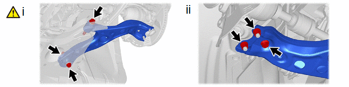
(1) Temporarily install the front lower No. 1 suspension arm sub-assembly LH to the front suspension crossmember sub-assembly with the 2 bolts and nut.
(2) Install the front lower No. 1 suspension arm sub-assembly LH to the front lower ball joint assembly LH with the bolt and 2 nuts.
Torque:
92 N·m {938 kgf·cm, 68 ft·lbf}
2. INSTALL FRONT WHEEL
Click here .gif)
3. STABILIZE SUSPENSION
|
|
Click here |
4. FULLY TIGHTEN FRONT LOWER NO. 1 SUSPENSION ARM SUB-ASSEMBLY
|
|
NOTICE: Because the nut has its own stopper, do not turn the nut. Tighten the bolt with the nut secured. |
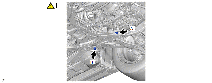
(1) Fully tighten the front lower No. 1 suspension arm sub-assembly with the 2 bolts.
Torque:
Bolt A :
240 N·m {2447 kgf·cm, 177 ft·lbf}
Bolt B :
135 N·m {1377 kgf·cm, 100 ft·lbf}
5. INSTALL REAR ENGINE UNDER COVER LH
6. INSTALL NO. 1 ENGINE UNDER COVER ASSEMBLY
Click here
7. INSPECT AND ADJUST FRONT WHEEL ALIGNMENT
Click here
8. PERFORM CALIBRATION (w/ Parking Assist Monitor System)
|
Parking assist monitor system |
|
|
Automatic headlight beam level control system |
|


