Toyota Corolla Cross Owners & Service Manuals

Toyota Corolla Cross: Front Shock Absorber

Inspection

INSPECTION

PROCEDURE

1. INSPECT FRONT SHOCK ABSORBER ASSEMBLY

(a) Compress and extend the front shock absorber assembly rod 4 times or more.

Standard:

When compressed and extended at a constant speed, the stroke of the shock absorber rod is smooth with no abnormal resistance or sounds. When extended, the shock absorber rod returns to its original position at a constant speed with no abnormal sounds.

HINT:

If there are any abnormalities, replace the front shock absorber assembly with a new one.

Disposal

DISPOSAL

CAUTION / NOTICE / HINT

CAUTION:

  • Always use a cloth to prevent shards of metal from flying about due to the release of pressurized gas.
  • Always wear safety glasses.
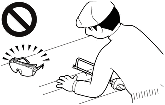
HINT:

The gas is colorless, odorless and non-poisonous.

PROCEDURE

1. DISPOSE OF FRONT SHOCK ABSORBER ASSEMBLY

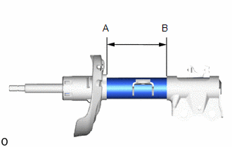
(a) Place the front shock absorber horizontally with the piston rod extended, and using a hacksaw, make a hole between (A) and (B) shown in the illustration to discharge the gas inside.

    READ NEXT:

     Front Stabilizer Bar

     Removal

    REMOVAL CAUTION / NOTICE / HINT COMPONENTS (REMOVAL) Procedure Part Name Code 1 FRONT SUSPENSION CROSSMEMBER SUB-ASSEMB

     Inspection

    INSPECTION PROCEDURE 1. INSPECT FRONT STABILIZER LINK ASSEMBLY (a) Inspect the turning torque of the ball joint. (1) Secure the front stabilizer link assembly in a vise using aluminum

    SEE MORE:

     Replacement

    REPLACEMENT CAUTION / NOTICE / HINT The necessary procedures (adjustment, calibration, initialization, or registration) that must be performed after parts are removed and installed, or replaced during the transfer case oil seal removal/installation are shown below. Necessary Procedures After

     Drive Motor "B" Phase U Current Sensor Signal Bias Level Out of Range / Zero Adjustment Failure (P0BF128,P0BF528,P0BF928)

    DTC SUMMARY MALFUNCTION DESCRIPTION These DTCs indicate that the current sensor value is abnormal. The cause of this malfunction may be one of the following: Inverter internal malfunction Current sensor malfunction Inverter with converter assembly internal circuit malfunction DESCRI

    © 2020-2025 Copyright www.tcorollacross.com PT NL