Toyota Corolla Cross: Installation
INSTALLATION
CAUTION / NOTICE / HINT
COMPONENTS (INSTALLATION)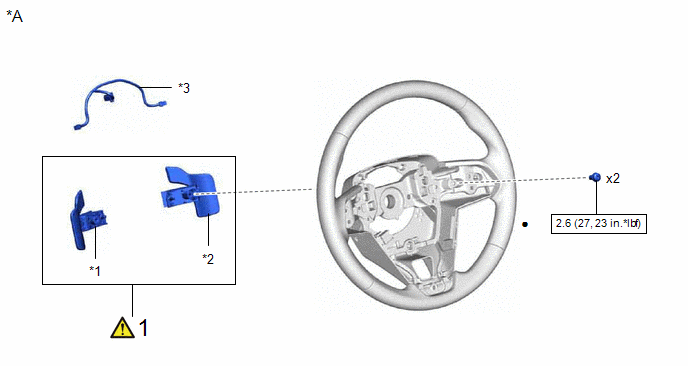
|
Procedure |
Part Name Code |
.png) |
.png) |
.png) |
|
|---|---|---|---|---|---|
|
1 |
SHIFT PADDLE SWITCH (TRANSMISSION SHIFT SWITCH ASSEMBLY) |
- |
|
- |
- |
|
*A |
w/ Shift Paddle Switch |
- |
- |
|
*1 |
NO. 1 TRANSMISSION SHIFT SWITCH ASSEMBLY |
*2 |
NO. 2 TRANSMISSION SHIFT SWITCH ASSEMBLY |
|
*3 |
NO. 1 SWITCH WIRE |
- |
- |
.png) |
N*m (kgf*cm, ft.*lbf): Specified torque |
● |
Non-reusable part |
|
★ |
Precoated part |
- |
- |
|
Procedure |
Part Name Code |
|
|
|
|
|---|---|---|---|---|---|
|
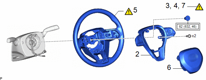
2 |
STEERING PAD SWITCH ASSEMBLY |
84250A |
- |
- |
- |
|
3 |
ALIGN FRONT WHEELS FACING STRAIGHT AHEAD |
- |
|
- |
- |
|
4 |
ADJUST SPIRAL CABLE WITH SENSOR SUB-ASSEMBLY |
- |
|
- |
- |
|
5 |
STEERING WHEEL ASSEMBLY |
45100 |
|
- |
- |
|
6 |
HORN BUTTON ASSEMBLY |
45130 |
- |
- |
- |
|
7 |
STEERING WHEEL CENTER POINT |
- |
|
- |
- |
.png) |
Tightening torque for "Major areas involving basic vehicle performance such as moving/turning/stopping" : N*m (kgf*cm, ft.*lbf) |
- |
- |
CAUTION / NOTICE / HINT
NOTICE:
- Do not remove/install the spiral cable with sensor sub-assembly with the auxiliary battery connected and the ignition switch (for Gasoline Model) or power switch (for HV Model) on (IG).
- Do not rotate the spiral cable with sensor sub-assembly without the steering wheel assembly installed, with the auxiliary battery connected and the ignition switch (for Gasoline Model) or power switch (for HV Model) on (IG).
- Ensure that the steering wheel assembly is installed and aligned straight when inspecting the steering sensor.
PROCEDURE
1. INSTALL SHIFT PADDLE SWITCH (TRANSMISSION SHIFT SWITCH ASSEMBLY) (w/ Shift Paddle Switch)
Click here .gif)
2. INSTALL STEERING PAD SWITCH ASSEMBLY
3. ALIGN FRONT WHEELS FACING STRAIGHT AHEAD
|
|
Click here |
4. ADJUST SPIRAL CABLE WITH SENSOR SUB-ASSEMBLY
Click here
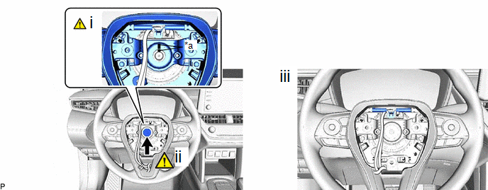
5. INSTALL STEERING WHEEL ASSEMBLY
|
*a |
Matchmark |
- |
- |
(1) Align the matchmarks on the steering wheel assembly and steering main shaft to install the steering wheel assembly.
(2) Using a 10 mm hexagon socket wrench, install the steering wheel assembly set bolt.
Torque:
62 N·m {632 kgf·cm, 46 ft·lbf}
(3) Connect each connector.
HINT:
As the illustration shown is an example, the actual details may differ.
6. INSTALL HORN BUTTON ASSEMBLY
Click here
7. CHECK STEERING WHEEL CENTER POINT
Click here


