
Toyota Corolla Cross Owners & Service Manuals

Toyota Corolla Cross: Installation

INSTALLATION

CAUTION / NOTICE / HINT

COMPONENTS (INSTALLATION)
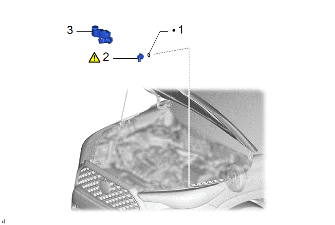
Procedure

Part Name Code

1

VACUUM SENSOR GROMMET

-

-

-

-

2

VACUUM SENSOR ASSEMBLY

89420H

-

-

3

BRAKE MASTER CYLINDER SUB-ASSEMBLY

47201

-

-

-

●

Non-reusable part

-

-

PROCEDURE

1. INSTALL VACUUM SENSOR GROMMET

2. INSTALL VACUUM SENSOR ASSEMBLY
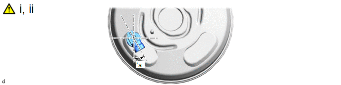
*a

30° +/- 6°

-

-

(1) Install the vacuum sensor assembly to the brake booster assembly so that the vacuum sensor assembly is angled as shown in the illustration.

(2) Connect the vacuum sensor assembly connector to the vacuum sensor assembly.

3. INSTALL BRAKE MASTER CYLINDER SUB-ASSEMBLY

Click here

    READ NEXT:

     Power Source & Network

    h1 {color:red;} h2 {color:blue;} h3 {color:green;}

     M20a-fks (battery / Charging)

     Battery Current Sensor

    SEE MORE:

     Wiper and Washer Switch Circuit

    DESCRIPTION The condition of the windshield wiper switch assembly is detected and sent to the steering sensor in this circuit. WIRING DIAGRAM PROCEDURE 1. READ VALUE USING GTS (STEERING ANGLE SENSOR) (a) Read the Data List according to the display on the GTS. Chassis > Steering A

     Drive Motor "B" Phase U Current Sensor Signal Bias Level Out of Range / Zero Adjustment Failure (P0BF128,P0BF528,P0BF928)

    DTC SUMMARY MALFUNCTION DESCRIPTION These DTCs indicate that the current sensor value is abnormal. The cause of this malfunction may be one of the following: Inverter internal malfunction Current sensor malfunction Inverter with converter assembly internal circuit malfunction DESCRI

    © 2020-2026 Copyright www.tcorollacross.com PT NL