Toyota Corolla Cross: Installation
INSTALLATION
CAUTION / NOTICE / HINT
COMPONENTS (INSTALLATION)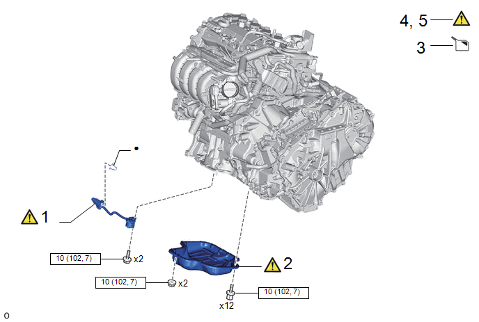
|
Procedure | Part Name Code |
.png) |
.png) |
 |
|---|---|---|---|---|---|
|
1 | ENGINE OIL LEVEL SENSOR |
89491 |
|
- | - |
|
2 | OIL PAN SUB-ASSEMBLY |
12101 |
|
- | - |
|
3 | ADD ENGINE OIL |
- | - |
|
- |
| 4 |
INSPECT FOR ENGINE OIL LEAK |
- |
|
- | - |
|
5 | CHECK ENGINE OIL LEVEL |
51410 |
|
- | - |
.png) |
N*m (kgf*cm, ft.*lbf): Specified torque |
● | Non-reusable part |

|
Procedure | Part Name Code |
|
|
| |
|---|---|---|---|---|---|
|
6 | NO. 1 ENGINE UNDER COVER ASSEMBLY |
51410 | - |
- | - |
|
|
N*m (kgf*cm, ft.*lbf): Specified torque |
- | - |
CAUTION / NOTICE / HINT
NOTICE:
This procedure includes the installation of small-head bolts. Refer to Small-Head Bolts of Basic Repair Hint to identify the small-head bolts.
Click here .gif)
PROCEDURE
1. INSTALL ENGINE OIL LEVEL SENSOR
(1) Using an 8 mm socket wrench, install the engine oil level sensor to the engine balancer assembly with the 2 bolts.
Torque:
10 N·m {102 kgf·cm, 7 ft·lbf}
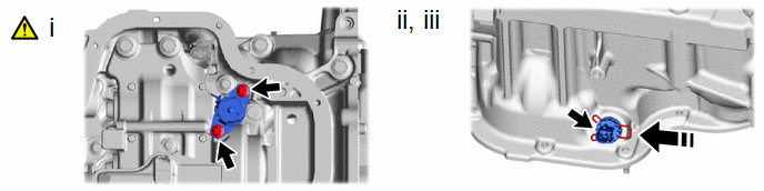
(2) Install a new clip to the engine oil level sensor.
(3) Connect the engine oil level sensor connector.
2. INSTALL OIL PAN SUB-ASSEMBLY
Click here
3. ADD ENGINE OIL
Click here
4. INSPECT FOR ENGINE OIL LEAK
|
|
Click here |
5. CHECK ENGINE OIL LEVEL
|
|
Click here |
6. INSTALL NO. 1 ENGINE UNDER COVER ASSEMBLY
Click here


