Toyota Corolla Cross: Installation
INSTALLATION
CAUTION / NOTICE / HINT
COMPONENTS (INSTALLATION)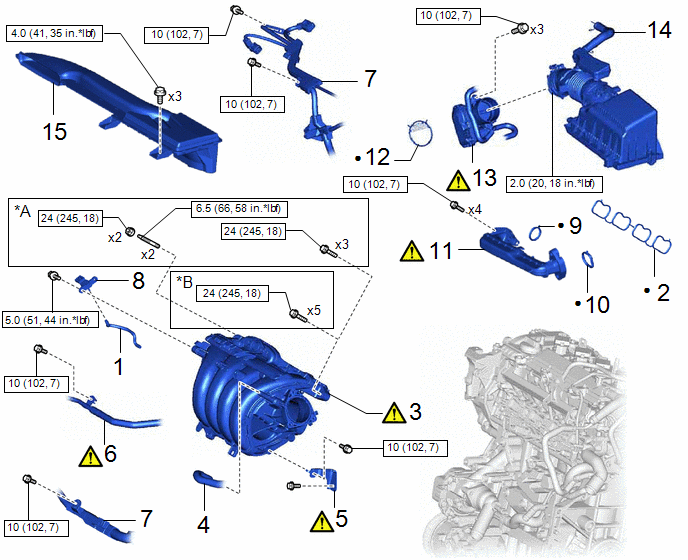
|
Procedure | Part Name Code |
.png) |
.png) |
 |
|---|---|---|---|---|---|
|
1 | VACUUM HOSE |
- | - |
- | - |
|
2 | NO. 1 INTAKE MANIFOLD TO HEAD GASKET |
17177 | - |
- | - |
|
3 | INTAKE MANIFOLD |
17111 | - |
- | - |
|
4 | NO. 1 FUEL VAPOR FEED HOSE |
23826 | - |
- | - |
|
5 | INTAKE MANIFOLD STAY |
17138B |
|
- | - |
|
6 | NO. 3 WATER BY-PASS PIPE |
16279 |
|
- | - |
|
7 | ENGINE WIRE |
82121 | - |
- | - |
|
8 | E.F.I. VACUUM SENSOR ASSEMBLY (MANIFOLD ABSOLUTE PRESSURE SENSOR) |
89421 | - |
- | - |
|
9 | EGR INLET GASKET |
25628 | - |
- | - |
|
10 | EGR VALVE ADAPTER GASKET |
25629 | - |
- | - |
|
11 | No .1 EGR PIPE SUB-ASSEMBKY |
25601 |
|
- | - |
|
12 | THROTTLE BODY GASKET |
22271 | - |
- | - |
|
13 | THROTTLE BODY WITH MOTOR ASSEMBLY |
22030 |
|
- | - |
|
14 | AIR CLEANER CAP WITH AIR CLEANER HOSE |
- | - |
- | - |
|
15 | INLET NO. 1 AIR CLEANER |
17751 | - |
- | - |
|
*A | w/ Stud bolt |
*B | w/o Stud bolt |
.png) |
N*m (kgf*cm, ft.*lbf): Specified torque |
● | Non-reusable part |
CAUTION / NOTICE / HINT
NOTICE:
This procedure includes the installation of small-head bolts. Refer to Small-Head Bolts of Basic Repair Hint to identify the small-head bolts.
Click here .gif)
PROCEDURE
1. INSTALL VACUUM HOSE
2. INSTALL NO. 1 INTAKE MANIFOLD TO HEAD GASKET
3. INSTALL INTAKE MANIFOLD
(a) w/o Stud bolt

(1) Temporarily install the intake manifold to the cylinder head sub-assembly with the 5 bolts.
(2) Tighten the 5 bolts in the order shown in the illustration.
Torque:
24 N·m {245 kgf·cm, 18 ft·lbf}
(b) w/ Stud bolt
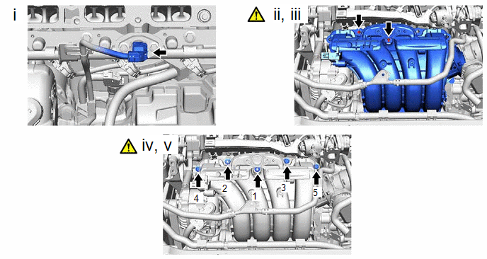
(1) Connect the fuel pressure sensor connector.
(2) Temporarily install the intake manifold to the cylinder head sub-assembly.
(3) Using an E8 "TORX" socket wrench, install the 2 stud bolts.
Torque:
6.5 N·m {66 kgf·cm, 58 in·lbf}
(4) Temporarily install the 3 bolts and 2 nuts.
(5) Tighten the 3 bolts and 2 nuts in the order shown in the illustration.
Torque:
24 N·m {245 kgf·cm, 18 ft·lbf}
4. CONNECT NO. 1 FUEL VAPOR FEED HOSE
5. INSTALL INTAKE MANIFOLD STAY

(1) Engage the guide to install the intake manifold stay.
(2) Install the bolt (B).
Torque:
21 N·m {214 kgf·cm, 15 ft·lbf}
(3) Using an 8 mm socket wrench, install the bolt (A).
Torque:
10 N·m {102 kgf·cm, 7 ft·lbf}
6. CONNECT NO. 3 WATER BY-PASS PIPE

(1) Using an 8 mm socket wrench, install the No. 3 water by-pass pipe to the intake manifold with the bolt.
Torque:
10 N·m {102 kgf·cm, 7 ft·lbf}
7. CONNECT ENGINE WIRE
Torque:
10 N·m {102 kgf·cm, 7 ft·lbf}
8. INSTALL E.F.I. VACUUM SENSOR ASSEMBLY (MANIFOLD ABSOLUTE PRESSURE SENSOR)
Click here
9. INSTALL EGR INLET GASKET
Click here
10. INSTALL EGR VALVE ADAPTER GASKET
Click here
11. INSTALL NO.1 EGR PIPE SUB-ASSEMBLY
Click here
12. INSTALL THROTTLE BODY GASKET
Click here
13. INSTALL THROTTLE BODY WITH MOTOR ASSEMBLY

(1) Using an 8 mm socket wrench, install the throttle body with motor assembly to the intake manifold with the 3 bolts.
Torque:
10 N·m {102 kgf·cm, 7 ft·lbf}
(2) Connect the throttle body with motor assembly connector.
14. INSTALL AIR CLEANER CAP WITH AIR CLEANER HOSE
Click here
15. INSTALL INLET NO. 1 AIR CLEANER
Click here


