Toyota Corolla Cross: Installation
INSTALLATION
CAUTION / NOTICE / HINT
COMPONENTS (INSTALLATION)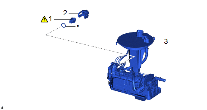
|
Procedure | Part Name Code |
.png) |
.png) |
 |
|---|---|---|---|---|---|
|
1 | FUEL MAIN VALVE ASSEMBLY |
23070 |
|
- | - |
|
2 | FUEL PRESSURE REGULATOR HOLDER |
23283B | - |
- | - |
|
3 | FUEL SUCTION TUBE WITH PUMP AND GAUGE ASSEMBLY |
77020A | - |
- | - |
|
● | Non-reusable part |
- | - |
PROCEDURE
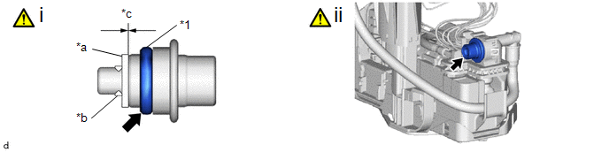
1. INSTALL FUEL MAIN VALVE ASSEMBLY
|
*1 | Fuel Main Valve Assembly |
- | - |
|
*a | Mesh |
*b | Mini-clip |
|
*c | No Clearance |
- | - |
(1) Apply gasoline to a new O-ring. Then install the O-ring to the fuel main valve assembly.
NOTICE:
Make sure that there is no clearance between the fuel main valve assembly and mesh.
(2) Install the fuel main valve assembly to the fuel suction tube with pump and gauge assembly.
NOTICE:
Make sure that the O-ring is not cut or pinched during installation.
2. INSTALL FUEL PRESSURE REGULATOR HOLDER
3. INSTALL FUEL SUCTION TUBE WITH PUMP AND GAUGE ASSEMBLY
Click here .gif)


