Toyota Corolla Cross: Installation
INSTALLATION
CAUTION / NOTICE / HINT
COMPONENTS (INSTALLATION)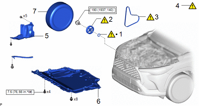
|
Procedure | Part Name Code |
.png) |
.png) |
 |
|---|---|---|---|---|---|
|
1 | TIMING CHAIN COVER OIL SEAL |
11301C |
|
- | - |
|
2 | CRANKSHAFT PULLEY ASSEMBLY |
13470 |
|
- | - |
|
3 | V-RIBBED BELT |
16361A |
|
- | - |
|
4 | INSPECT FOR ENGINE OIL LEAK |
- |
|
- | - |
|
5 | REAR ENGINE UNDER COVER RH |
51443C | - |
- | - |
|
6 | NO. 1 ENGINE UNDER COVER ASSEMBLY |
51410 | - |
- | - |
|
7 | FRONT WHEEL RH |
- | - |
- | - |
.png) |
Tightening torque for "Major areas involving basic vehicle performance such as moving/turning/stopping" : N*m (kgf*cm, ft.*lbf) |
.png) |
N*m (kgf*cm, ft.*lbf): Specified torque |
|
● | Non-reusable part |
- | - |
PROCEDURE
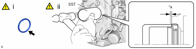
1. INSTALL TIMING CHAIN COVER OIL SEAL
|
*a | 0 to 2 mm |
- | - |
(1) Apply MP grease to the lip of a new timing chain cover oil seal.
NOTICE:
- Keep the lip free from foreign matter.
- Do not allow MP grease to contact the dust seal.
(2) Using SST and a hammer, tap in the timing chain cover oil seal.
SST: 09223-00010
Standard Depth:
0 to 2 mm (0 to 0.0787 in.) (From the edge of the No. 2 timing chain cover assembly)
NOTICE:
Do not tap in the timing chain cover oil seal at an angle.
2. INSTALL CRANKSHAFT PULLEY ASSEMBLY
|
|
Click here |
3. INSTALL V-RIBBED BELT
|
|
Click here |
4. INSPECT FOR ENGINE OIL LEAK
Click here
.gif)
5. INSTALL REAR ENGINE UNDER COVER RH
Click here
6. INSTALL NO. 1 ENGINE UNDER COVER ASSEMBLY
Click here
7. INSTALL FRONT WHEEL RH
Click here


