Toyota Corolla Cross: Installation
INSTALLATION
CAUTION / NOTICE / HINT
COMPONENTS (INSTALLATION)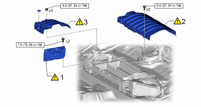
|
Procedure | Part Name Code |
.png) |
.png) |
 |
|---|---|---|---|---|---|
|
1 | BATTERY ECU ASSEMBLY |
89890A |
|
- | - |
|
2 | UPPER HV BATTERY COVER SUB-ASSEMBLY |
- |
|
- | - |
|
3 | NO. 1 HYBRID BATTERY SHIELD SUB-ASSEMBLY |
G920Q |
|
- | - |
.png) |
N*m (kgf*cm, ft.*lbf): Specified torque |
- | - |
|
Procedure | Part Name Code |
|
|
| |
|---|---|---|---|---|---|
|
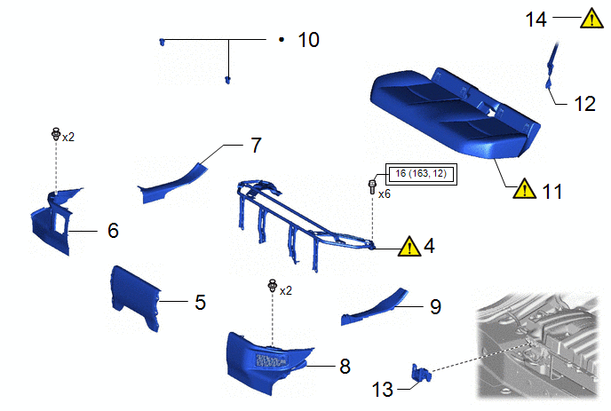
4 | REAR SEAT CUSHION LEG SUB-ASSEMBLY |
71033 |
|
- | - |
|
5 | REAR UNDER COVER |
76971G | - |
- | - |
|
6 | REAR UNDER SIDE COVER RH |
76973F | - |
- | - |
|
7 | REAR DOOR SCUFF PLATE RH |
67917A | - |
- | - |
|
8 | REAR UNDER SIDE COVER LH |
76974F | - |
- | - |
|
9 | REAR DOOR SCUFF PLATE LH |
67918A | - |
- | - |
|
10 | REAR SEAT CUSHION LOCK HOOK |
72693 | - |
- | - |
|
11 | BENCH TYPE REAR SEAT CUSHION ASSEMBLY |
- |
|
- | - |
|
12 | REAR CENTER SEAT OUTER BELT ASSEMBLY |
73350C | - |
- | - |
|
13 | SERVICE PLUG GRIP |
G3834 | - |
- | - |
|
14 | CURRENT SENSOR OFFSET LEARNING |
- |
|
- | - |
.png) |
Tightening torque for "Major areas involving basic vehicle performance such as moving/turning/stopping" : N*m (kgf*cm, ft.*lbf) |
● | Non-reusable part |
PROCEDURE
1. INSTALL BATTERY ECU ASSEMBLY
|
|
CAUTION: Be sure to wear insulated gloves and protective goggles. NOTICE:
|
Torque:
7.5 N·m {76 kgf·cm, 66 in·lbf}
2. INSTALL UPPER HV BATTERY COVER SUB-ASSEMBLY
|
|
CAUTION: Be sure to wear insulated gloves and protective goggles. |
Torque:
9.5 N·m {97 kgf·cm, 84 in·lbf}
3. INSTALL NO. 1 HYBRID BATTERY SHIELD SUB-ASSEMBLY
|
|
Click here |
4. INSTALL REAR SEAT CUSHION LEG SUB-ASSEMBLY
Click here
.gif)
5. INSTALL REAR UNDER COVER
Click here
6. INSTALL REAR UNDER SIDE COVER RH
7. INSTALL REAR DOOR SCUFF PLATE RH
8. INSTALL REAR UNDER SIDE COVER LH
9. INSTALL REAR DOOR SCUFF PLATE LH
10. INSTALL REAR SEAT CUSHION LOCK HOOK
Click here
11. INSTALL BENCH TYPE REAR SEAT CUSHION ASSEMBLY
Click here
12. CONNECT REAR CENTER SEAT OUTER BELT ASSEMBLY
Click here
13. INSTALL SERVICE PLUG GRIP
Click here
14. CURRENT SENSOR OFFSET LEARNING
HINT:
Perform this procedure when the HV battery junction block assembly or battery ECU assembly has been replaced.
Click here


