Toyota Corolla Cross: Combination Switch
Inspection
INSPECTION
PROCEDURE
1. INSPECT EV DRIVE MODE SWITCH (COMBINATION SWITCH ASSEMBLY)
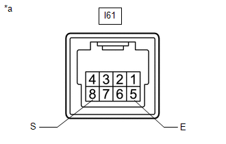
(a) Check the resistance.
| (1) Measure the resistance according to the value(s) in the table below.
Standard Resistance: |
Tester Connection |
Condition | Specified Condition | |
I61-8 (S) - I61-5 (E) |
EV drive mode switch (combination switch assembly) being pushed and held |
Below 50 Ω | |
EV drive mode switch (combination switch assembly) not pushed |
10 kΩ or higher | If the result is not as specified, replace the EV drive mode switch (combination switch assembly). |
 |
|
*a | Component without harness connected
(EV Drive Mode Switch (Combination Switch Assembly)) | | |
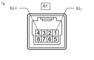
(b) Check illumination.
| (1) Apply auxiliary battery voltage between the terminals of the switch, and check the illumination condition of the EV drive mode switch (combination switch assembly).
Standard: |
Measurement Condition |
Specified Condition | |
Auxiliary battery positive (+) → I61-4 (ILL+) Auxiliary battery negative (-) → I61-1 (ILL-) |
Illuminates | If the result is not as specified, replace the EV drive mode switch (combination switch assembly). |
 |
|
*a | Component without harness connected
(EV Drive Mode Switch (Combination Switch Assembly)) | | |
2. INSPECT DRIVE MODE SELECT SWITCH (COMBINATION SWITCH ASSEMBLY)
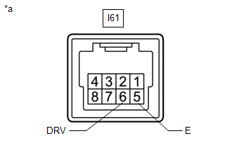
(a) Check the resistance.
| (1) Measure the resistance according to the value(s) in the table below.
Standard Resistance: |
Tester Connection |
Condition | Specified Condition | |
I61-6 (DRV) - I61-5 (E) |
Drive mode select switch (combination switch assembly) being pushed and held |
Below 50 Ω | |
Drive mode select switch (combination switch assembly) not pushed |
10 kΩ or higher | If the result is not as specified, replace the drive mode select switch (combination switch assembly). |
 |
|
*a | Component without harness connected
(Drive Mode Select Switch (Combination Switch Assembly)) | | |
(b) Check illumination.
| (1) Apply auxiliary battery voltage between the terminals of the switch, and check the illumination condition of the drive mode select switch (combination switch assembly).
Standard: |
Measurement Condition |
Specified Condition | |
Auxiliary battery positive (+) → I61-4 (ILL+) Auxiliary battery negative (-) → I61-1 (ILL-) |
Illuminates | If the result is not as specified, replace the drive mode select switch (combination switch assembly). |
|
|
|
*a | Component without harness connected
(Drive Mode Select Switch (Combination Switch Assembly)) | | |
READ NEXT:
ComponentsCOMPONENTS ILLUSTRATION
*1 RESERVE TANK CAP
*2 DRAIN COCK PLUG
*3 NO. 1 ENGINE UNDER COVER ASSEMBLY
- -
N*m (kgf*cm, ft.*lbf): Sp
REMOVAL CAUTION / NOTICE / HINT COMPONENTS (REMOVAL)
Procedure Part Name Code
1 PRECAUTION
-
- -
2 SERVICE PLUG GRIP
SEE MORE:
DTC SUMMARY MALFUNCTION DESCRIPTION These DTCs are stored when the motor temperature sensor output is abnormal. The cause of this malfunction may be one of the following: Motor temperature sensor malfunction
Internal motor temperature sensor malfunction
Open or short in motor temperature
PARTS LOCATION ILLUSTRATION
*1 HEADLIGHT ASSEMBLY RH
*2 HEADLIGHT ASSEMBLY LH
*3 SIDE TURN SIGNAL LIGHT ASSEMBLY RH
*4 SIDE TURN SIGNAL LIGHT ASSEMBLY LH
*5 REAR COMBINATION LIGHT ASSEMBLY RH
- TURN SIGNAL LIGHT *6
REAR COMBINATION LIGHT AS


