Toyota Corolla Cross: Installation
INSTALLATION
CAUTION / NOTICE / HINT
COMPONENTS (INSTALLATION)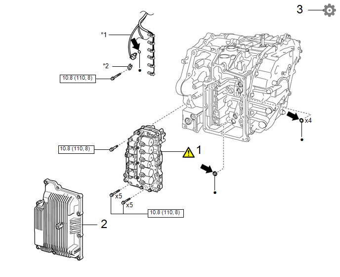
|
Procedure |
Part Name Code |
.png) |
.png) |
.png) |
|
|---|---|---|---|---|---|
|
1 |
TRANSMISSION VALVE BODY ASSEMBLY |
35410J |
|
- |
- |
|
2 |
TRANSAXLE SIDE COVER SUB-ASSEMBLY |
35015Y |
- |
- |
- |
|
3 |
RESET MEMORY |
- |
- |
- |
|
|
*1 |
TRANSMISSION WIRE |
*2 |
TEMPERATURE SENSOR CLAMP |
.png) |
N*m (kgf*cm, ft.*lbf): Specified torque |
● |
Non-reusable part |
.png) |
Toyota Genuine CVT Fluid FE |
- |
- |
CAUTION / NOTICE / HINT
HINT:
Shift shock may increase after replacing the transmission valve body assembly. In this case, shift shock will reduce as the vehicle is driven.
PROCEDURE
1. INSTALL TRANSMISSION VALVE BODY ASSEMBLY
|
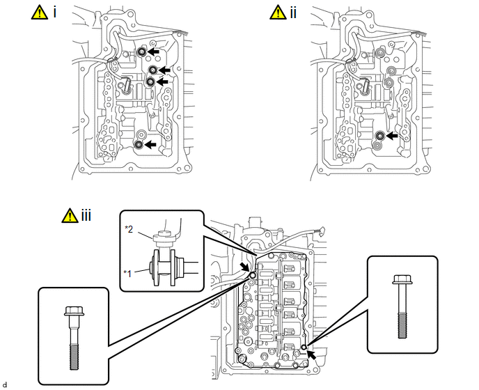
*1 |
Manual Valve |
*2 |
Manual Valve Link Lever Sub-assembly |
(1) Coat 4 new transaxle case gaskets with Toyota Genuine CVT fluid FE and install them to the transaxle case sub-assembly.
(2) Coat a new front oil pump cover gasket with Toyota Genuine CVT fluid FE and install it to the transaxle case sub-assembly.
(3) Align the slit portion of the manual valve and the manual valve link lever sub-assembly as shown in the illustration, and temporarily install the transmission valve body assembly to the transaxle case sub-assembly with the 2 bolts.
Bolt Length:
40 mm (1.57 in.)
|
|
Toyota Genuine CVT Fluid FE |
- |
- |
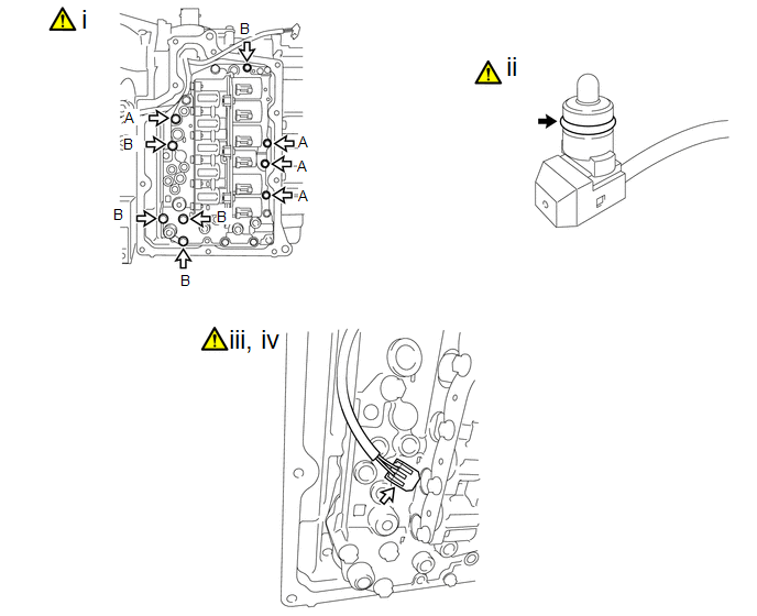
(1) Temporarily install the 9 bolts.
Bolt Length:
|
Bolt (A) |
Bolt (B) |
|---|---|
|
40 mm (1.57 in.) |
55 mm (2.17 in.) |
(2) Coat a new O-ring with Toyota Genuine CVT fluid FE and install it to the temperature sensor.
(3) Connect the temperature sensor to the transmission valve body assembly.
NOTICE:
To prevent it from being pinched between the transmission valve body assembly and the transaxle side cover sub-assembly, do not let the transmission wire ride up over the area shown in the illustration.
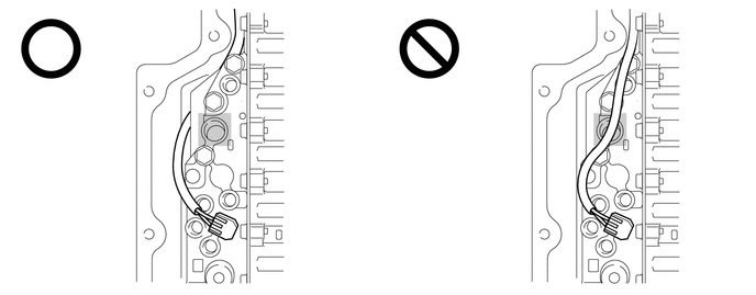
.png) |
Do not let transmission wire protrude into this area. |
- |
- |
(4) Temporarily install the temperature sensor clamp to the transmission valve body assembly with the bolt.
Bolt Length:
55 mm (2.17 in.)
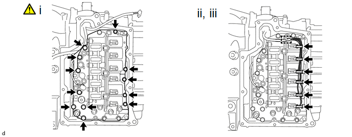
(1) Fully tighten the 12 bolts.
Torque:
10.8 N·m {110 kgf·cm, 8 ft·lbf}
(2) Connect the 6 solenoid valve connectors.
(3) Engage the clamp to connect the transmission wire to the solenoid lock plate.
2. INSTALL TRANSAXLE SIDE COVER SUB-ASSEMBLY
Click here .gif)
3. RESET MEMORY
NOTICE:
If continuously variable transaxle parts have been replaced, refer to Parts Replacement Compensation Table to determine if any additional operations are necessary.
Click here


