Toyota Corolla Cross: Installation
Toyota Corolla Cross (2022-2026) Service Manual / Drivetrain / Axle And Differential / Steering Knuckle / Installation
INSTALLATION
CAUTION / NOTICE / HINT
COMPONENTS (INSTALLATION)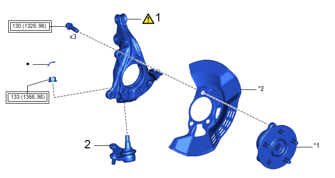
|
Procedure |
Part Name Code |
.png) |
.png) |
.png) |
|
|---|---|---|---|---|---|
|
1 |
STEERING KNUCKLE |
43212 |
|
- |
- |
|
2 |
FRONT LOWER BALL JOINT ASSEMBLY |
43340A |
- |
- |
- |
|
*1 |
FRONT AXLE HUB SUB-ASSEMBLY |
*2 |
FRONT DISC BRAKE DUST COVER |
.png) |
Tightening torque for "Major areas involving basic vehicle performance such as moving/turning/stopping": N*m (kgf*cm, ft.*lbf) |
● |
Non-reusable part |
CAUTION / NOTICE / HINT
HINT:
- Use the same procedure for the RH side and LH side.
- The following procedure is for the LH side.
PROCEDURE
1. INSTALL STEERING KNUCKLE
.png)
(1) Secure the steering knuckle between aluminum plates in a vise.
NOTICE:
Do not overtighten the vise.
(2) Install the front axle hub sub-assembly and front disc brake dust cover to the steering knuckle with the 3 bolts.
Torque:
130 N·m {1326 kgf·cm, 96 ft·lbf}
2. INSTALL FRONT LOWER BALL JOINT ASSEMBLY
Click here .gif)


