
Toyota Corolla Cross: Installation
INSTALLATION
CAUTION / NOTICE / HINT
COMPONENTS (INSTALLATION)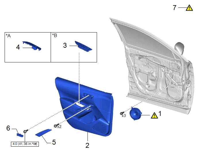
|
Procedure |
Part Name Code |
.png) |
.png) |
.png) |
|
|---|---|---|---|---|---|
|
1 |
FRONT NO. 1 SPEAKER ASSEMBLY |
86160 |
|
- |
- |
|
2 |
FRONT DOOR TRIM BOARD SUB-ASSEMBLY |
67602 |
- |
- |
- |
|
3 |
MULTIPLEX NETWORK MASTER SWITCH ASSEMBLY WITH FRONT DOOR UPPER ARMREST BASE PANEL |
- |
- |
- |
- |
|
4 |
POWER WINDOW REGULATOR SWITCH ASSEMBLY WITH FRONT DOOR UPPER ARMREST BASE PANEL |
- |
- |
- |
- |
|
5 |
DOOR ASSIST GRIP COVER |
74646 |
- |
- |
- |
|
6 |
FRONT DOOR INSIDE HANDLE BEZEL PLUG |
69284F |
- |
- |
- |
|
7 |
INSPECT POWER WINDOW OPERATION |
- |
|
- |
- |
|
*A |
for Front Passenger Side |
*B |
for Driver Side |
 |
N*m (kgf*cm, ft.*lbf): Specified torque |
- |
- |
CAUTION / NOTICE / HINT
HINT:
- Use the same procedure for the RH side and LH side.
- The following procedure is for the LH side.
PROCEDURE
1. INSTALL FRONT NO. 1 SPEAKER ASSEMBLY
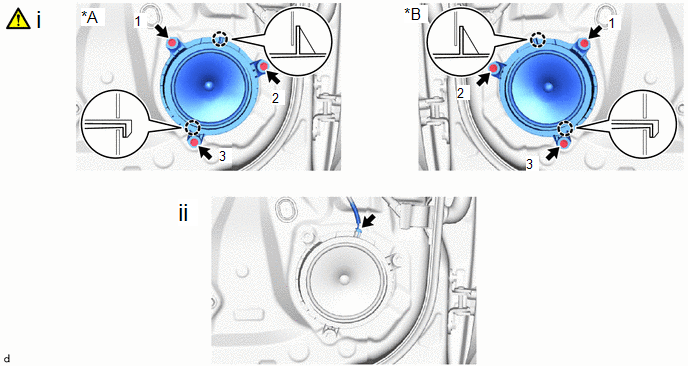
|
*A |
for LH Side |
*B |
for RH Side |
(1) Engage the claws to install the front No. 1 speaker assembly with the 3 screws.
NOTICE:
Install the screws in the order shown in the illustration.
(2) Connect the connector.
2. INSTALL FRONT DOOR TRIM BOARD SUB-ASSEMBLY
3. INSTALL MULTIPLEX NETWORK MASTER SWITCH ASSEMBLY WITH FRONT DOOR UPPER ARMREST BASE PANEL (for Driver Side)
4. INSTALL POWER WINDOW REGULATOR SWITCH ASSEMBLY WITH FRONT DOOR UPPER ARMREST BASE PANEL (for Front Passenger Side)
5. INSTALL DOOR ASSIST GRIP COVER
6. INSTALL FRONT DOOR INSIDE HANDLE BEZEL PLUG
7. INSPECT POWER WINDOW OPERATION
Click here .gif)


