Toyota Corolla Cross: Inspection
INSPECTION
PROCEDURE
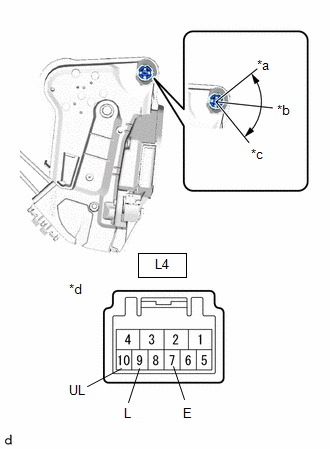
1. INSPECT FRONT DOOR LOCK WITH MOTOR ASSEMBLY LH
| (a) Check the door lock motor operation. (1) Apply auxiliary battery voltage to the motor connector and check the operation of the door lock motor. OK:
If the result is not as specified, replace the front door lock with motor assembly LH. |
|
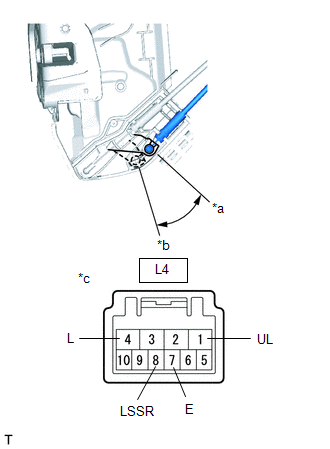
(b) Check the operation of the door unlock detection switch.
(1) Measure the resistance according to the value(s) in the table below.
Standard Resistance:
|
Tester Connection | Condition |
Specified Condition |
|---|---|---|
|
L4-7 (E) - L4-8 (LSSR) |
Lock | 10 kΩ or higher |
|
Unlock | Below 1 Ω |
If the result is not as specified, replace the front door lock with motor assembly LH.
| (c) Check the resistance of the door key lock and unlock switch. (1) Measure the resistance according to the value(s) in the table below. Standard Resistance:
If the result is not as specified, replace the front door lock with motor assembly LH. |
|
2. INSPECT FRONT DOOR LOCK WITH MOTOR ASSEMBLY RH
| (a) Check the door lock motor operation. (1) Apply auxiliary battery voltage to the motor connector and check the operation of the door lock motor. OK:
If the result is not as specified, replace the front door lock with motor assembly RH. |
|
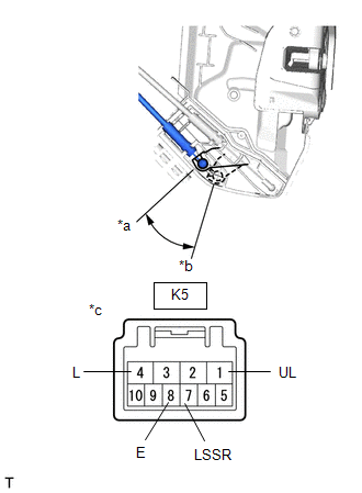
(b) Check the operation of the door unlock detection switch.
(1) Measure the resistance according to the value(s) in the table below.
Standard Resistance:
|
Tester Connection | Condition |
Specified Condition |
|---|---|---|
|
K5-7 (LSSR) - K5-8 (E) |
Lock | 10 kΩ or higher |
|
Unlock | Below 1 Ω |
If the result is not as specified, replace the front door lock with motor assembly RH.


