Toyota Corolla Cross: Inspection
INSPECTION
PROCEDURE
1. INSPECT POWER WINDOW REGULATOR MOTOR ASSEMBLY LH
(a) Check the operation.
|
(1) Connect a positive (+) lead from the auxiliary battery to connector terminal N2-2 (B).
NOTICE: Do not connect a positive (+) lead from the auxiliary battery to any terminal other than terminal N2-2 (B) to avoid damaging the pulse sensor inside the motor. |
 |
|
*a | Component without harness connected
(Power Window Regulator Motor Assembly LH) | |
*b | Motor Gear | |
*c | Clockwise | |
*d | Counterclockwise | | |
(2) Connect a negative (-) lead from the auxiliary battery to connector terminals N2-1 (GND) and N2-7 (DOWN) or N2-10 (UP).
(3) Check that the motor gear rotates smoothly as follows:
OK:
|
Measurement Condition | Specified Condition |
- Connect a positive (+) lead from the auxiliary battery to terminal N2-2 (B), connect a negative (-) lead from the auxiliary battery to terminal N2-1 (GND), and keep them connected for 3 seconds or more.
- With terminals N2-2 (B) and N2-1 (GND) connected, connect a negative (-) lead from the auxiliary battery to terminal N2-10 (UP).
| Motor gear rotates clockwise |
- Connect a positive (+) lead from the auxiliary battery to terminal N2-2 (B), connect a negative (-) lead from the auxiliary battery to terminal N2-1 (GND), and keep them connected for 3 seconds or more.
- With terminals N2-2 (B) and N2-1 (GND) connected, connect a negative (-) lead from the auxiliary battery to terminal N2-7 (DOWN).
| Motor gear rotates counterclockwise |
- If the result is not as specified, replace the power window regulator motor assembly LH.
CAUTION:
Initialize the power window control system after installing the rear door window regulator assembly.
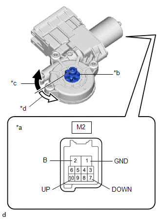
2. INSPECT POWER WINDOW REGULATOR MOTOR ASSEMBLY RH
(a) Check the operation.
| (1) Connect a positive (+) lead from the auxiliary battery to connector terminal M2-2 (B).
NOTICE: Do not connect a positive (+) lead from the auxiliary battery to any terminal other than terminal M2-2 (B) to avoid damaging the pulse sensor inside the motor. |
 |
|
*a | Component without harness connected
(Power Window Regulator Motor Assembly RH) | |
*b | Motor Gear | |
*c | Clockwise | |
*d | Counterclockwise | | |
(2) Connect a negative (-) lead from the auxiliary battery to connector terminals M2-1 (GND) and M2-7 (DOWN) or M2-10 (UP).
(3) Check that the motor gear rotates smoothly as follows:
OK:
|
Measurement Condition | Specified Condition |
- Connect a positive (+) lead from the auxiliary battery to terminal M2-2 (B), connect a negative (-) lead from the auxiliary battery to terminal M2-1 (GND), and keep them connected for 3 seconds or more.
- With terminals M2-2 (B) and M2-1 (GND) connected, connect a negative (-) lead from the auxiliary battery to terminal M2-10 (UP).
| Motor gear rotates counterclockwise |
- Connect a positive (+) lead from the auxiliary battery to terminal M2-2 (B), connect a negative (-) lead from the auxiliary battery to terminal M2-1 (GND), and keep them connected for 3 seconds or more.
- With terminals M2-2 (B) and M2-1 (GND) connected, connect a negative (-) lead from the auxiliary battery to terminal M2-7 (DOWN).
| Motor gear rotates clockwise |
- If the result is not as specified, replace the power window regulator motor assembly RH.
CAUTION:
Initialize the power window control system after installing the rear door window regulator assembly.
READ NEXT:
INSTALLATION CAUTION / NOTICE / HINT COMPONENTS (INSTALLATION)
Procedure Part Name Code
1 POWER WINDOW REGULATOR MOTOR ASSEMBLY
85710F
- -
2
REMOVAL CAUTION / NOTICE / HINT COMPONENTS (REMOVAL)
Procedure Part Name Code
1 DECK TRIM SIDE PANEL ASSEMBLY
64740C -
- -
2 ROOF SIDE INNER GAR
SEE MORE:
DESCRIPTION
Using the current from the TCM, the shift solenoid valve SLU controls the lock-up
clutch pressure, and performs lock-up and flex lock-up control.
DTC No.
Detection Item
DTC Detection Condition
Trouble Area
MIL
Memory
Replace the battery with a
new one if it is depleted.
As the key may be damaged
if the following procedure is
not performed properly, it is
recommended that key battery
replacement be performed
by your Toyota
dealer.
■If the key battery is depleted
The following symptoms may occur:
The smart ke


