Toyota Corolla Cross: Inspection
INSPECTION
PROCEDURE
1. INSPECT POWER WINDOW REGULATOR MOTOR ASSEMBLY LH
(a) Check the operation.
|
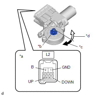
(1) Connect a positive (+) lead from the auxiliary battery to connector terminal L2-2 (B).
NOTICE: Do not connect a positive (+) lead from the auxiliary battery to any terminal other than terminal L2-2 (B) to avoid damaging the pulse sensor inside the motor. |
 |
|
*a | Component without harness connected
(Power Window Regulator Motor Assembly LH) | |
*b | Motor Gear | |
*c | Clockwise | |
*d | Counterclockwise | | |
(2) Connect a negative (-) lead from the auxiliary battery to connector terminals L2-1 (GND) and L2-7 (DOWN) or L2-10 (UP).
(3) Check that the motor gear rotates smoothly as follows:
OK:
|
Measurement Condition | Specified Condition |
- Connect a positive (+) lead from the auxiliary battery to terminal L2-2 (B), connect a negative (-) lead from the auxiliary battery to terminal L2-1 (GND), and keep them connected for 3 seconds or more.
- With terminals L2-2 (B) and L2-1 (GND) connected, connect a negative (-) lead from the auxiliary battery to terminal L2-10 (UP).
| Motor gear rotates clockwise |
- Connect a positive (+) lead from the auxiliary battery to terminal L2-2 (B), connect a negative (-) lead from the auxiliary battery to terminal L2-1 (GND), and keep them connected for 3 seconds or more.
- With terminals L2-2 (B) and L2-1 (GND) connected, connect a negative (-) lead from the auxiliary battery to terminal L2-7 (DOWN).
| Motor gear rotates counterclockwise |
- If the result is not as specified, replace the power window regulator motor assembly LH.
CAUTION:
Initialize the power window control system after installing the front door window regulator assembly.
2. INSPECT POWER WINDOW REGULATOR MOTOR ASSEMBLY RH
(a) Check the operation.
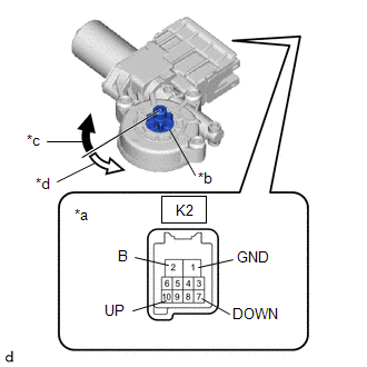
| (1) Connect a positive (+) lead from the auxiliary battery to connector terminal K2-2 (B).
NOTICE: Do not connect a positive (+) lead from the auxiliary battery to any terminal other than terminal K2-2 (B) to avoid damaging the pulse sensor inside the motor. |
 |
|
*a | Component without harness connected
(Power Window Regulator Motor Assembly RH) | |
*b | Motor Gear | |
*c | Clockwise | |
*d | Counterclockwise | | |
(2) Connect a negative (-) lead from the auxiliary battery to connector terminals K2-1 (GND) and K2-7 (DOWN) or K2-10 (UP).
(3) Check that the motor gear rotates smoothly as follows:
OK:
|
Measurement Condition | Specified Condition |
- Connect a positive (+) lead from the auxiliary battery to terminal K2-2 (B), connect a negative (-) lead from the auxiliary battery to terminal K2-1 (GND), and keep them connected for 3 seconds or more.
- With terminals K2-2 (B) and K2-1 (GND) connected, connect a negative (-) lead from the auxiliary battery to terminal K2-10 (UP).
| Motor gear rotates counterclockwise |
- Connect a positive (+) lead from the auxiliary battery to terminal K2-2 (B), connect a negative (-) lead from the auxiliary battery to terminal K2-1 (GND), and keep them connected for 3 seconds or more.
- With terminals K2-2 (B) and K2-1 (GND) connected, connect a negative (-) lead from the auxiliary battery to terminal K2-7 (DOWN).
| Motor gear rotates clockwise |
- If the result is not as specified, replace the power window regulator motor assembly RH.
CAUTION:
Initialize the power window control system after installing the front door window regulator assembly.
READ NEXT:
INSTALLATION CAUTION / NOTICE / HINT COMPONENTS (INSTALLATION)
Procedure Part Name Code
1 POWER WINDOW REGULATOR MOTOR ASSEMBLY
85720D
- -
2
REMOVAL CAUTION / NOTICE / HINT COMPONENTS (REMOVAL)
Procedure Part Name Code
1 REAR DOOR GLASS SUB-ASSEMBLY
68104
- -
2 REAR DOOR WINDOW
SEE MORE:
DESCRIPTION The throttle actuator is operated by the ECM and opens and closes the throttle valve using gears.
The opening angle of the throttle valve is detected by the throttle position sensor, which is mounted on the throttle body with motor assembly. The throttle position sensor provides feedba
PARTS LOCATION ILLUSTRATION
*1 ECM
*2 NO. 1 ENGINE ROOM RELAY BLOCK AND NO. 1 JUNCTION BLOCK ASSEMBLY
- INJ FUSE *3
IGNITION COIL ASSEMBLY
*4 SPARK PLUG


