Toyota Corolla Cross: Inspection
INSPECTION
PROCEDURE
1. INSPECT PRELOAD
|
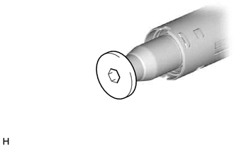
(a) Using a 10 mm hexagon socket wrench, install the steering wheel assembly
set bolt to the steering main shaft.
NOTICE:
- Do not apply excessive torque to the steering wheel assembly set
bolt by using a tool such as an impact wrench.
- The steering wheel assembly set bolt is used for turning the steering
main shaft during inspection of the steering main shaft rotating torque.
- Remove the steering wheel assembly set bolt after performing this
inspection.
|
|
|
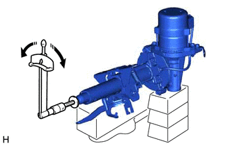
(b) Secure the steering column assembly in a vise using aluminum plates,
cloths and wooden blocks.
NOTICE:
- Do not overtighten the vise, as the steering column assembly may
become deformed.
- Support the steering column assembly with wooden blocks or similar
items to ensure that it does not fall.
|
|
(c) Using a torque wrench, turn the steering main shaft at a constant rate of
approximately 1 revolution every 4 seconds and measure the preload.
Preload:
1.1 to 2.3 N*m (12 to 23 kgf*cm, 10 to 20 in.*lbf)
.png) |
Turn
|
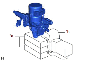
(d) If the preload is not as specified, replace the power steering ECU assembly
or electric power steering column sub-assembly with a new one.
(e) Remove the steering wheel assembly set bolt.
2. INSPECT STEERING COLUMN ASSEMBLY
|
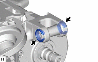
(a) Check that the 2 bushings are securely installed to the steering
column assembly.
|
|
(b) If the bushings are deformed, missing or damaged, replace the electric power
steering column sub-assembly with a new one.
READ NEXT:
REASSEMBLY
CAUTION / NOTICE / HINT
COMPONENTS (REASSEMBLY)
Procedure
Part Name Code
1
IGNITION OR STARTER SWITCH ASSEMB
INSTALLATION
CAUTION / NOTICE / HINT
COMPONENTS (INSTALLATION)
Procedure
Part Name Code
1
ALIGN FRONT WHEELS FACING STR
Removal
REMOVAL
CAUTION / NOTICE / HINT
COMPONENTS (REMOVAL)
Procedure
Part Name Code
1
SWITCH BASE
55449
SEE MORE:
PROBLEM SYMPTOMS TABLE HINT: Use the table below to help determine the cause of problem symptoms. If multiple suspected areas are listed, the potential causes of the symptoms are listed in order of probability in the "Suspected Area" column of the table. Check each symptom by checking the suspected
INSPECTION PROCEDURE 1. INSPECT FUEL PUMP
(a) Measure the resistance according to the value(s) in the table below.
Standard Resistance:
Tester Connection Specified Condition
U - V 0.05 to 3.0 Ω
V - W 0.05 to 3.0 Ω
U - W 0.05 to 3.0 Ω
If th