Toyota Corolla Cross: Reassembly
REASSEMBLY
CAUTION / NOTICE / HINT
COMPONENTS (REASSEMBLY)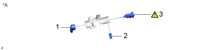
|
Procedure |
Part Name Code |
.png) |
.png) |
.png) |
|
|---|---|---|---|---|---|
|
1 |
IGNITION OR STARTER SWITCH ASSEMBLY |
84450 |
- |
- |
- |
|
2 |
UN-LOCK WARNING SWITCH ASSEMBLY |
84052 |
- |
- |
- |
|
3 |
IGNITION SWITCH LOCK CYLINDER ASSEMBLY |
- |
|
- |
- |
.gif)
|
*A |
w/o Smart Key System |
- |
- |
|
Procedure |
Part Name Code |
|
|
|
|
|---|---|---|---|---|---|
|
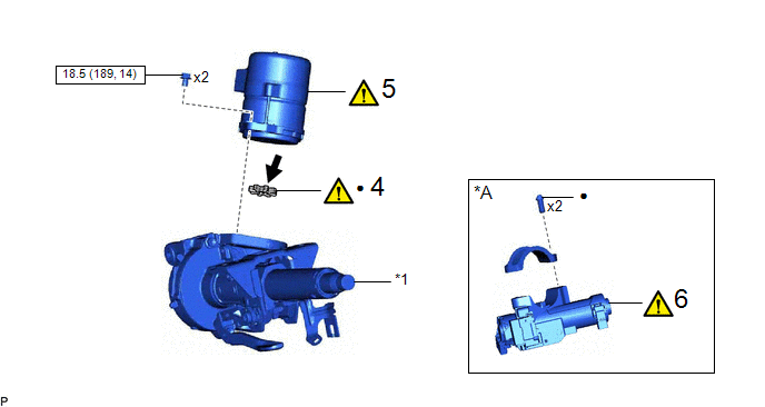
4 |
ELECTRIC POWER STEERING MOTOR SHAFT DAMPER |
45254B |
|
- |
- |
|
5 |
POWER STEERING ECU ASSEMBLY |
89650 |
|
- |
- |
|
6 |
UPPER STEERING COLUMN BRACKET WITH SWITCH ASSEMBLY |
45020 |
|
- |
- |
|
*A |
w/o Smart Key System |
- |
- |
|
*1 |
ELECTRIC POWER STEERING COLUMN SUB-ASSEMBLY |
- |
- |
 |
N*m (kgf*cm, ft.*lbf): Specified torque |
● |
Non-reusable part |
.png) |
Grease |
- |
- |
CAUTION / NOTICE / HINT
NOTICE:
- Do not drop the power steering ECU assembly, strike it with tools or subject it to impacts.
- If the power steering ECU assembly is subjected to an impact, replace it with a new one.
- Do not pull the wire harness.
- Do not allow any moisture to come into contact with the power steering ECU assembly.
- Do not loosen any bolts not mentioned in the procedure.
- Do not allow any foreign matter to contaminate the power steering ECU assembly.
PROCEDURE
1. INSTALL IGNITION OR STARTER SWITCH ASSEMBLY (w/o Smart Key System)
2. INSTALL UN-LOCK WARNING SWITCH ASSEMBLY (w/o Smart Key System)
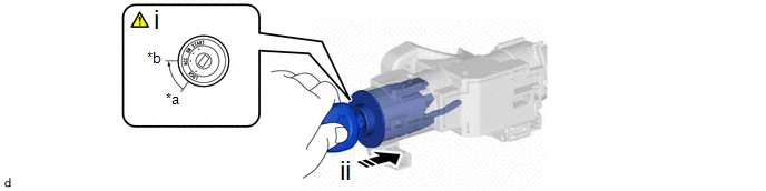
3. INSTALL IGNITION SWITCH LOCK CYLINDER ASSEMBLY (w/o Smart Key System)
|
*a |
LOCK |
*b |
ACC |
.png) |
Install in this direction |
- |
- |
(1) Turn the ignition switch to ACC.
(2) Install the ignition switch lock cylinder assembly to the upper steering column bracket assembly.
4. INSTALL ELECTRIC POWER STEERING MOTOR SHAFT DAMPER
|
|
Click here |
5. INSTALL POWER STEERING ECU ASSEMBLY
|
|
Click here |
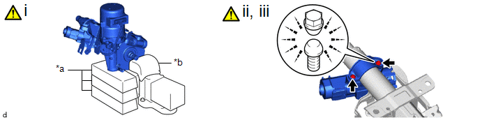
6. INSTALL UPPER STEERING COLUMN BRACKET WITH SWITCH ASSEMBLY (w/o Smart Key System)
|
*a |
Wooden Block |
*b |
Cloth |
(1) Secure the steering column assembly in a vise using aluminum plates, cloths and wooden blocks.
NOTICE:
- Do not overtighten the vise, as the steering column assembly may become deformed.
- Secure the power steering ECU assembly so that it is upright.
- Support the steering column assembly with wooden blocks or similar items to ensure that it does not fall.
(2) Temporarily install the upper steering column bracket with switch assembly and upper steering column clamp with 2 new steering lock set bolts.
(3) Tighten the 2 steering lock set bolts until the bolt head breaks off.


