Toyota Corolla Cross: Inspection
INSPECTION
PROCEDURE
1. INSPECT OIL PRESSURE AND TEMPERATURE SENSOR
(a) Check the oil pressure and temperature sensor output voltage.
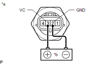
| (1) Apply 5 V between terminals 3 (VC) and 2 (GND).
NOTICE:
- Be careful when connecting the leads as the oil pressure and temperature sensor may be damaged if the leads are connected to the wrong terminals.
- Do not apply more than 6 V to terminals 3 (VC) or 2 (GND).
HINT: If a stable power supply is not available, connect 4 nickel-metal hydride batteries (1.2 V each) or equivalent in series. |
 |
|
*a | Component without harness connected
(Oil Pressure and Temperature Sensor) | |
*b | Voltage Applied between Terminals | | |
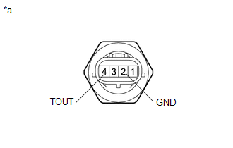
| (2) Measure the voltage between terminals. Standard Voltage: |
Tester Connection | Condition |
Specified Condition | |
4 (TOUT) - 2 (GND) |
20°C (68°F) | Approximately 1.5 to 2.5 V* |
*: The output voltage changes depending on the voltage applied to the terminals.
If the result is not as specified, replace the oil pressure and temperature sensor. |
 |
|
*a | Component without harness connected
(Oil Pressure and Temperature Sensor) | | |
READ NEXT:
INSTALLATION CAUTION / NOTICE / HINT COMPONENTS (INSTALLATION)
Procedure Part Name Code
1 OIL PRESSURE AND TEMPERATURE SENSOR
89448D
- -
REMOVAL CAUTION / NOTICE / HINT COMPONENTS (REMOVAL)
Procedure Part Name Code
1 REAR ENGINE UNDER COVER RH
51443C -
- -
2 OIL PRESSURE
SEE MORE:
DESCRIPTION
If the system information stored by the skid control ECU (brake
actuator assembly) is corrupted, this DTC is output.
DTC No.
Detection Item
DTC Detection Condition
Trouble Area
C059746
Brake System Control Module
DESCRIPTION
Detection Item
Symptom
Trouble Area
Tire Pressure Monitor ECU Communication Stop Mode
Communication stop for "Tire Pressure" is indicated on the "Communication
Bus Check" screen of the GTS.
Click her


