Toyota Corolla Cross: Inspection
INSPECTION
PROCEDURE
1. INSPECT NO.1 TRACTION BATTERY DEVICE BOX ASSEMBLY
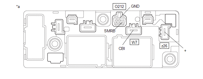
(a) Inspect SMRB:
(1) Measure the resistance according to the value(s) in the table below.
|
*a | Component without harness connected (No. 1 Traction Battery Device Box Assembly) |
- | - |
Standard Resistance:
|
Tester Connection | Condition |
Specified Condition |
|---|---|---|
|
W7-1 (CBI) - z26-1 (+) |
Auxiliary battery voltage not applied between terminals O212-4 (SMRB) and O212-2 (GND) |
10 kΩ or higher |
|
W7-1 (CBI) - z26-1 (+) |
Auxiliary battery voltage applied between terminals O212-4 (SMRB) and O212-2 (GND) |
Below 1 Ω |
(2) Measure the resistance according to the value(s) in the table below.
Standard Resistance:
|
Tester Connection | Condition |
Specified Condition |
|---|---|---|
|
O212-4 (SMRB) - O212-2 (GND) |
-40 to 80°C (-40 to 176°F) |
25.0 to 59.0 Ω |
If the result is not as specified, replace the No. 1 traction battery device box assembly.
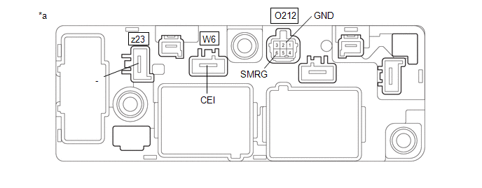
(b) Inspect SMRG:
(1) Measure the resistance according to the value(s) in the table below.
|
*a | Component without harness connected (No. 1 Traction Battery Device Box Assembly) |
- | - |
Standard Resistance:
|
Tester Connection | Condition |
Specified Condition |
|---|---|---|
|
W6-1 (CEI) - z23-1 (-) |
Auxiliary battery voltage not applied between terminals O212-6 (SMRG) and O212-2 (GND) |
10 kΩ or higher |
|
W6-1 (CEI) - z23-1 (-) |
Auxiliary battery voltage applied between terminals O212-6 (SMRG) and O212-2 (GND) |
Below 1 Ω |
(2) Measure the resistance according to the value(s) in the table below.
Standard Resistance:
|
Tester Connection | Condition |
Specified Condition |
|---|---|---|
|
O212-6 (SMRG) - O212-2 (GND) |
-40 to 80°C (-40 to 176°F) |
25.0 to 59.0 Ω |
If the result is not as specified, replace the No. 1 traction battery device box assembly.


