Toyota Corolla Cross: Inspection
INSPECTION
PROCEDURE
1. INSPECT FRONT NO. 1 SPEAKER ASSEMBLY LH (w/o Stereo Component Amplifier)
(a) With the front No. 1 speaker assembly LH installed, check that there is no looseness or other abnormalities.
(b) Check that there is no foreign matter in the front No. 1 speaker assembly LH, no tears on the front No. 1 speaker assembly LH cone or other abnormalities.
|
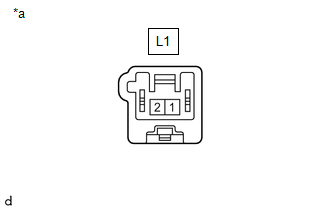
(c) Measure the resistance of the front No. 1 speaker assembly LH. Standard Resistance:
If the result is not as specified, replace the front No. 1 speaker assembly LH. |
|
2. INSPECT FRONT NO. 1 SPEAKER ASSEMBLY RH (w/o Stereo Component Amplifier)
(a) With the front No. 1 speaker assembly RH installed, check that there is no looseness or other abnormalities.
(b) Check that there is no foreign matter in the front No. 1 speaker assembly RH, no tears on the front No. 1 speaker assembly RH cone or other abnormalities.
|
(c) Measure the resistance of the front No. 1 speaker assembly RH. Standard Resistance:
If the result is not as specified, replace the front No. 1 speaker assembly RH. |
|

3. INSPECT FRONT NO. 1 SPEAKER ASSEMBLY LH (w/ Stereo Component Amplifier)
(a) With the front No. 1 speaker assembly LH installed, check that there is no looseness or other abnormalities.
(b) Check that there is no foreign matter in the front No. 1 speaker assembly LH, no tears on the front No. 1 speaker assembly LH cone or other abnormalities.
|
(c) Measure the resistance of the front No. 1 speaker assembly LH. Standard Resistance:
If the result is not as specified, replace the front No. 1 speaker assembly LH. |
|
4. INSPECT FRONT NO. 1 SPEAKER ASSEMBLY RH (w/ Stereo Component Amplifier)
(a) With the front No. 1 speaker assembly RH installed, check that there is no looseness or other abnormalities.
(b) Check that there is no foreign matter in the front No. 1 speaker assembly RH, no tears on the front No. 1 speaker assembly RH cone or other abnormalities.
|
(c) Measure the resistance of the front No. 1 speaker assembly RH. Standard Resistance:
If the result is not as specified, replace the front No. 1 speaker assembly RH. |
|


