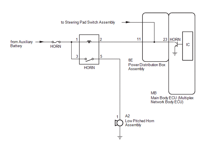
Toyota Corolla Cross: Horn Circuit
DESCRIPTION
When the theft deterrent system is switched from the armed state to the alarm sounding state, the main body ECU (multiplex network body ECU) transmits a signal to cause the horn to sound at intervals of 0.4 seconds.
WIRING DIAGRAM
CAUTION / NOTICE / HINT
NOTICE:
- Before replacing the main body ECU (multiplex network body ECU), refer to Registration.
- for HEV Model:
Click here
.gif)
- for Gasoline Model:
Click here
- for HEV Model:
- Inspect the fuses for circuits related to this system before performing the following procedure.
PROCEDURE
|
1. | INSPECT HORN |
(a) Press the horn switch and check if the horn sounds.
|
Result | Proceed to |
|---|---|
|
Horn sounds | A |
|
Horn does not sound | B |
| B |
.gif) | GO TO HORN SYSTEM |
|
.gif)
| 2. |
INSPECT POWER DISTRIBUTION BOX ASSEMBLY |
(a) Remove the main body ECU (multiplex network body ECU).
Click here
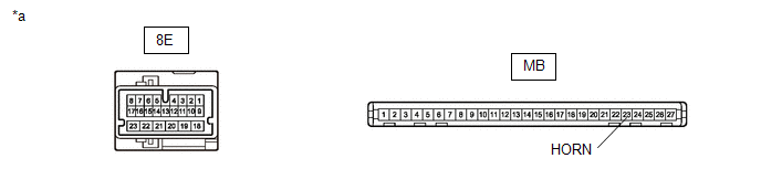
|
*a | Component without harness connected (Power Distribution Box Assembly) |
- | - |
(b) Disconnect the 8E power distribution box assembly connector.
(c) Measure the resistance according to the value(s) in the table below.
Standard Resistance:
|
Tester Connection | Condition |
Specified Condition |
|---|---|---|
|
8E-11 - MB-23 (HORN) |
Always | Below 1 Ω |
| NG | | REPLACE POWER DISTRIBUTION BOX ASSEMBLY |
|
| 3. |
CHECK HARNESS AND CONNECTOR (HORN RELAY - POWER DISTRIBUTION BOX ASSEMBLY) |
| (a) Remove the HORN relay from the No. 1 engine room relay block. |
|
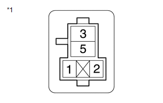
(b) Measure the resistance according to the value(s) in the table below.
Standard Resistance:
|
Tester Connection | Condition |
Specified Condition |
|---|---|---|
|
HORN relay holder terminal 2 - 8E-11 |
Always | Below 1 Ω |
|
HORN relay holder terminal 2 or 8E-11 - Other terminals and body ground |
Always | 10 kΩ or higher |
| OK | | REPLACE MAIN BODY ECU (MULTIPLEX NETWORK BODY ECU) |
| NG | | REPAIR OR REPLACE HARNESS OR CONNECTOR |


