Toyota Corolla Cross: Emergency Call Switch Illumination Circuit
WIRING DIAGRAM
CAUTION / NOTICE / HINT
NOTICE:
- Depending on the parts that are replaced during vehicle inspection or
maintenance, performing initialization, registration or calibration may
be needed. Refer to Precaution for Safety Connect System.
Click here
.gif)
- Inspect the fuses for circuits related to this system before performing the following procedure.
PROCEDURE
|
1. |
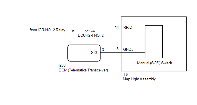
CHECK HARNESS AND CONNECTOR (MAP LIGHT ASSEMBLY POWER SOURCE) |
(a) Disconnect the I200 DCM (telematics transceiver) connector.
(b) Disconnect the T6 map light assembly (manual [SOS] switch) connector.
(c) Measure the voltage according to the value(s) in the table below.
Standard Voltage:
|
Tester Connection |
Switch Condition |
Specified Condition |
|---|---|---|
|
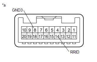
T6-14 (RRID) - Body Ground |
Ignition switch ON |
11 to 14 V |
(d) Measure the resistance according to the value(s) in the table below.
Standard Resistance:
|
Tester Connection |
Condition |
Specified Condition |
|---|---|---|
|
I200-3 (SIG-) - T6-8 (GND3) |
Always |
Below 1 Ω |
|
I200-3 (SIG-) or T6-8 (GND3) - Body ground |
Always |
10 kΩ or higher |
| NG | .gif)
|
REPAIR OR REPLACE HARNESS OR CONNECTOR |
|
.gif)
|
2. |
INSPECT MAP LIGHT ASSEMBLY (MANUAL [SOS] SWITCH) |
|
(a) Remove the map light assembly (manual [SOS] switch). Click here |
|
(b) Apply auxiliary battery voltage to the connector.
|
Measurement Condition |
Condition |
Specified Condition |
|---|---|---|
|
Auxiliary battery positive (+) → 14 (RRID) Auxiliary battery negative (-) → 8 (GND3) |
Always |
Manual (SOS) switch illumination comes on |
(c) Check if the manual (SOS) switch illumination comes on.
OK:
The manual (SOS) switch illumination comes on.
| NG |
|
REPLACE MAP LIGHT ASSEMBLY (MANUAL (SOS) SWITCH) |
|
|
3. |
REPLACE DCM (TELEMATICS TRANSCEIVER) |
(a) Replace the DCM (telematics transceiver) with a new one.
Click here
NOTICE:
- The ignition switch must be off.
- Do not exchange the DCM (telematics transceiver) with one from another vehicle.
| NEXT |
|
PERFORM DCM ACTIVATION |


