Toyota Corolla Cross: Electronic Brake Booster Control Module "A" System Internal Failure (C121F04,C14C9A3)
DESCRIPTION
If there is a malfunction in the power source circuit, the electric brake booster (brake booster with master cylinder assembly) stores a DTC, and ABS, brake assist, regenerative braking, etc. operation is prohibited by fail-safe control.
When a malfunction in the auxiliary battery, charging circuit, etc. results in a voltage differential between the +BS terminal and the internal circuit terminal of the electric brake booster (brake booster with master cylinder assembly), this DTC is stored.
When the voltage between the +BS terminal and the internal circuit terminal of the electric brake booster (brake booster with master cylinder assembly) returns to normal, this DTC is cleared.
|
DTC No. |
Detection Item |
DTC Detection Condition |
Trouble Area |
MIL |
DTC Output from |
Note |
|---|---|---|---|---|---|---|
|
C121F04 |
Electronic Brake Booster Control Module "A" System Internal Failure |
A voltage difference of 1.0 V or more is detected between the +BS terminal and the IGR terminal, and the voltage of the IGR terminal is 3.2 V or less. |
|
Comes on |
Brake Booster |
|
|
C14C9A3 |
Electronic Brake Booster Control Module "A" System Voltage High |
The +BS terminal voltage is less than 27.5 V for 0.2 seconds or more. |
|
Comes on |
Brake Booster |
|
MONITOR DESCRIPTION
C121F (Case 2 to 9):- When the electronically controlled brake system is starting, operating or shutting down and an ECU internal malfunction is detected, the electric brake booster (brake booster with master cylinder assembly) illuminates the MIL and stores this DTC.
- When the electronically controlled brake system is operating or shutting down, the motor is not operating, the supply voltage of the electric brake booster (brake booster with master cylinder assembly) exceeds a certain value and the difference between the supply voltage of the electric brake booster (brake booster with master cylinder assembly) and the voltage of the motor drive circuit exceeds a certain value, the electric brake booster (brake booster with master cylinder assembly) illuminates the MIL and stores this DTC.
- When the electronically controlled brake system is operating or shutting down, the motor is not operating, the motor drive circuit voltage is less than a certain value, and the difference between the supply voltage of the electric brake booster (brake booster with master cylinder assembly) and voltage of the motor drive circuit exceeds a certain value, the electric brake booster (brake booster with master cylinder assembly) illuminates the MIL and stores this DTC.
- When the electronically controlled brake system is operating and the power supply voltage of the electric brake booster (brake booster with master cylinder assembly) exceeds a certain value, the electric brake booster (brake booster with master cylinder assembly) illuminates the MIL and stores this DTC.
MONITOR STRATEGY
|
Related DTCs |
C121F (Case 2 to 9): ECU internal monitoring (brake booster with master cylinder assembly) C121F (Case 10): Booster supply voltage / motor drive circuit voltage divider monitor C121F (Case 11): Motor drive circuit supply circuit monitor C14CB: UBB voltage monitoring (over voltage shutdown level) |
|
Required Sensors/Components(Main) |
Electric brake booster (brake booster with master cylinder assembly) |
|
Required Sensors/Components(Related) |
Electric brake booster (brake booster with master cylinder assembly) |
|
Frequency of Operation |
Continuous |
|
Duration |
-: C121F (Case 2 and 9) Immediately up to 0.08 seconds: C121F (Case 3 and 8) 0.01 seconds: C121F (Case 11) 0.01 to 0.084 seconds: C121F (Case 4) 0.06 seconds: C121F (Case 6 and 7) 0.12 seconds: C121F (Case 5) 0.2 seconds: C121F (Case 10) and C14CB |
|
MIL Operation |
Immediately: C121F (Case 2 to 11) 2 driving cycles: C14CB |
|
Sequence of Operation |
None |
TYPICAL ENABLING CONDITIONS
|
Monitor runs whenever the following DTCs are not stored |
TMC's intellectual property |
|
Other conditions belong to TMC's intellectual property |
- |
TYPICAL MALFUNCTION THRESHOLDS
|
TMC's intellectual property |
- |
COMPONENT OPERATING RANGE
|
TMC's intellectual property |
- |
CONFIRMATION DRIVING PATTERN
NOTICE:
When performing the normal judgment procedure, make sure that the driver door is closed and is not opened at any time during the procedure.
HINT:
- After repair has been completed, clear the DTC and then check that the vehicle has returned to normal by performing the following All Readiness check procedure.
- When clearing the permanent DTCs, refer to the "CLEAR PERMANENT DTC" procedure.
- Connect the GTS to the DLC3.
- Turn the ignition switch to ON and turn the GTS on.
- Clear the DTCs (even if no DTCs are stored, perform the clear DTC procedure).
- Turn the ignition switch off.
- Turn the ignition switch to ON (READY) and turn the GTS on.
- Wait for 1 second or more. [*]
HINT:
[*]: Normal judgment procedure.
The normal judgment procedure is used to complete DTC judgment and also used when clearing permanent DTCs.
- Enter the following menus: Chassis / Brake Booster / Utility / All Readiness.
- Check the DTC judgment result.
HINT:
- If the judgment result shows NORMAL, the system is normal.
- If the judgment result shows ABNORMAL, the system has a malfunction.
- If the judgment result shows INCOMPLETE, perform driving pattern again.
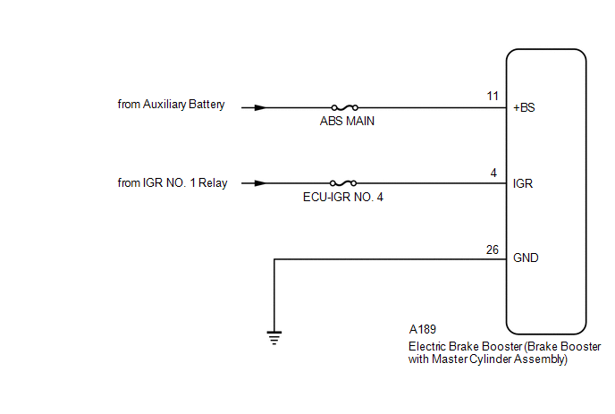
WIRING DIAGRAM
CAUTION / NOTICE / HINT
NOTICE:
Inspect the fuses for circuits related to this system before performing the following procedure.
PROCEDURE
|
1. |
CHECK HARNESS AND CONNECTOR (+BS TERMINAL) |
|
(a) Make sure that there is no looseness at the locking part and the connecting part of the connectors. OK: The connector is securely connected. |
|
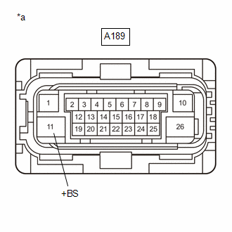
(b) Disconnect the A189 electric brake booster (brake booster with master cylinder assembly) connector.
(c) Check both the connector case and the terminals for deformation and corrosion.
OK:
No deformation or corrosion.
(d) Measure the voltage according to the value(s) in the table below.
Standard Voltage:
|
Tester Connection |
Condition |
Specified Condition |
|---|---|---|
|
A189-11 (+BS) - Body ground |
Always |
11 to 14 V |
| NG | .gif)
|
REPAIR OR REPLACE HARNESS OR CONNECTOR |
|
.gif)
|
2. |
CHECK HARNESS AND CONNECTOR (IGR TERMINAL) |
|
(a) Make sure that there is no looseness at the locking part and the connecting part of the connectors. OK: The connector is securely connected. |
|
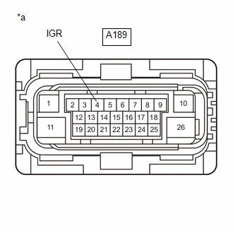
(b) Disconnect the A189 electric brake booster (brake booster with master cylinder assembly) connector.
(c) Check both the connector case and the terminals for deformation and corrosion.
OK:
No deformation or corrosion.
(d) Measure the voltage according to the value(s) in the table below.
Standard Voltage:
|
Tester Connection |
Condition |
Specified Condition |
|---|---|---|
|
A189-4 (IGR) - Body ground |
Ignition switch ON |
11 to 14 V |
| OK |
|
REPLACE BRAKE BOOSTER WITH MASTER CYLINDER ASSEMBLY |
| NG |
|
REPAIR OR REPLACE HARNESS OR CONNECTOR |


