Toyota Corolla Cross: ECU Power Source Circuit
DESCRIPTION
When the ignition switch is turned to ON, auxiliary battery voltage is applied to terminal MREL of the ECM through the coil of the EFI-MAIN relay. This causes the EFI-MAIN relay to close, which supplies power to terminal +B of the TCM.
WIRING DIAGRAM
Refer to DTC U010087.
Click here .gif)
CAUTION / NOTICE / HINT
NOTICE:
- Inspect the fuses for circuits related to this system before performing the following procedure.
- Perform registration and/or initialization when parts related to the continuously
variable transaxle system are replaced.
Click here
PROCEDURE
|
1. |
CHECK HARNESS AND CONNECTOR (TCM - BODY GROUND) |
(a) Disconnect the C80 TCM connector.
(b) Measure the resistance according to the value(s) in the table below.
Standard Resistance:
|
Tester Connection |
Condition |
Specified Condition |
|---|---|---|
|
C80-2 (E1) - Body ground |
Always |
Below 1 Ω |
(c) Connect the C80 TCM connector.
| NG | .gif) |
REPAIR OR REPLACE HARNESS OR CONNECTOR |
|
.gif)
|
2. |
INSPECT ECU TERMINAL VOLTAGE (+B TERMINAL) |
|
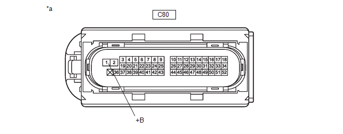
*a |
Front view of wire harness connector (to TCM) |
- |
- |
(a) Disconnect the C80 TCM connector.
(b) Turn the ignition switch to ON.
(c) Measure the voltage according to the value(s) in the table below.
Standard Voltage:
|
Tester Connection |
Condition |
Specified Condition |
|---|---|---|
|
C80-1 (+B) - Body ground |
Ignition switch ON |
11 to 14 V |
(d) Connect the C80 TCM connector.
| OK | |
CHECK FOR INTERMITTENT PROBLEMS Click here Click here |
|
|
3. |
CHECK HARNESS AND CONNECTOR (TCM - EFI-MAIN NO. 1 RELAY) |
(a) Remove the EFI-MAIN NO. 1 relay from the No. 1 engine room relay block assembly.
(b) Disconnect the C80 TCM connector.
(c) Measure the resistance according to the value(s) in the table below.
Standard Resistance (Check for Open):
|
Tester Connection |
Condition |
Specified Condition |
|---|---|---|
|
C80-1 (+B) - 3 (EFI-MAIN NO. 1 Relay) |
Always |
Below 1 Ω |
|
C80-1 (+B) or 3 (EFI-MAIN NO. 1 Relay) - Body ground |
Always |
10 kΩ or higher |
(d) Connect the C80 TCM connector.
(e) Install the EFI-MAIN NO. 1 relay to the No. 1 engine room relay block assembly.
| OK | |
GO TO ECM POWER SOURCE CIRCUIT (ENGINE CONTROL SYSTEM / SFI SYSTEM) |
| NG | |
REPAIR OR REPLACE HARNESS OR CONNECTOR |


